This article provides an overview of the hardware and software architecture of a sinusoidal field oriented controller for a brushless DC motor (BLDC). Brushless DC motors are becoming much more common in automotive applications due to their improvements in performance, efficiency, and reliability over brushed motors.
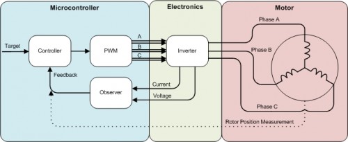
A brushless motor has to be commutated electronically, meaning that power must be applied to each of the 3 phase windings at just the right time as the rotor spins. This requires an inverter which is capable of controlling the voltage at each motor phase. The inverter is driven by 6 PWM outputs from the microcontroller, controlling whether each motor phase is connected to power or ground. In order to determine the correct PWM states, the controller needs to know the rotor position (angle). This can either be measured with a sensor, or it can be estimated from current and/or voltage feedback from the inverter. For field oriented control, current feedback is required regardless of whether there is a rotor position sensor.
The diagram below shows the major components of the BLDC control system.

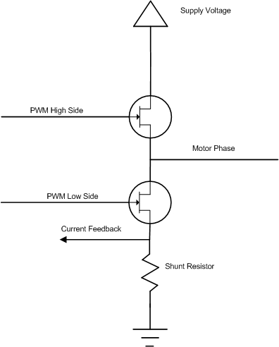
The inverter controls each motor phase voltage with a pair of FET’s which can apply either power or ground. The PWM outputs from the microcontroller are paired together such that one controls the high side FET and the other controls the low side FET. The PWM pairs are operated together in a complementary switching scheme, where they are never both on at the same time. The phase current can be measured through a shunt resistor on the ground side of the inverter circuit. In this setup, current flows through the shunt resistor when the low-side FET is turned on. The diagram below shows an example circuit for 1 leg of the inverter. This circuit is repeated for the other 2 motor phases.

There are many micro-controllers designed specifically for motor control which may have some or all of the following features:
The PWM outputs can be paired together to do complementary switching. Since each motor phase is connected to 2 FET’s, they must be controlled as a pair. Both FET’s must never be on at the same time; when one is on, the other must be off.
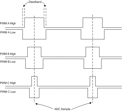
The PWM pairs have a configurable deadband between the complementary switch states. The deadband is a time delay between turning one FET off and turning the other on. This prevents current shoot-through on the FET’s by preventing any overlap where both FET’s could be on simultaneously.
The PWM clocks can be synchronized with each other and center-aligned. For a FOC system, the phase current is typically required on at least 2 of the 3 motor phases, and is measured through a shunt resistor on the ground side of the inverter circuit. Since current only flows through the shunt resistor when the low-side FET is on, the PWM’s need to be aligned so that all of the current measurements can be sampled at the same time.
The ADC conversions can be triggered by the PWM clock. This allows the feedback signals to be sampled exactly when current is flowing through the shunt resistors.
The diagram below shows an example of the complementary, center-aligned PWM signals which would drive the inverter.

The control algorithm transforms the motor phase currents to the reference frame of the rotor. This transformation allows the sinusoidal phase currents to be controlled as DC quantities. The two axes in this coordinate system are the direct axis, which is aligned with the rotor and the quadrature axis, which is perpendicular to the rotor. The current vector of each axis is controlled independently, which allows the angle between the resultant vector and the rotor to also be controlled. The q-axis controls the motor torque, the d-axis controls the motor flux linkage. Maximum torque occurs when the resultant current vector is aligned with the quadrature axis (ie. Id = 0).
Since this whole control scheme is based on the rotor frame of reference, the rotor position estimator is the key component and it must be accurate. One method of estimating the position is to use a back-emf observer. As the motor speed increases, it creates a back-emf which produces a current that opposes that driven by the inverter. A simple model of the motor can be implemented based on this equation.

In the next part in the series we will more closely investigate how to estimate the rotor position with this equation.
