CANopen is a CAN-based communication protocol. It comprises higher-layer protocols and profile specifications to exchange data between multiple devices on a network. Today it is used in various applications, such as medical equipment, off-road vehicles, maritime electronics, railway applications, and building automation.
OpenECU provides a reference design containing six blocks to implement a CANopen communication network. These blocks are used to configure the CAN bus, monitor CAN bus status, transmit, and receive CAN messages. The CANopen reference design is built upon the OpenECU Simulink blockset.
Communication
CANopen devices use several types of messages for communication, such as, PDO, NMT, SYNC and EMCY messages. Despite the differences at the application level, the standard CAN message format is always the fundamental structure for exchanging information. This enables OpenECU to use its existing CAN blocks to act as a master CANopen device and communicate with CANopen slave devices.
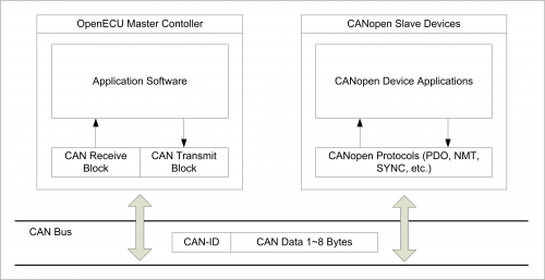
Typical CANopen System
The reference design model is used as an example to show how OpenECU can be used to realize communication and control of CANopen devices. This model has been validated in a motor control system which has a CANopen compliant inverter controller. OpenECU serves as the master controller and sends commands via CAN to the inverter, which acts as a CANopen slave, and provides feedback to the master. This configuration may be found in a hybrid or electric vehicle utilizing an inverter that uses the CANopen protocol.
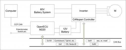
Example 1: PDO
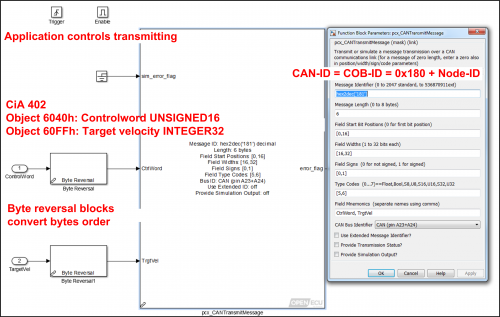
Process data objects (PDOs) are used in CANopen for broadcasting high-priority control and status information. For example, the master OpenECU controller uses PDOs to send motor speed mode commands to the slave the motor controller. The slave motor controller in turn uses PDOs to feedback the actual motor status. A PDO consists of a single CAN frame and provides up to 8 byte of application data. The PDO objects need to belong to the CANopen object dictionary and both devices must have the same configuration.

The reference design model sends and receives process data using OpenECU CAN blocks. Note that OpenECU CAN blocks use the Motorola byte order and byte reversal block may need to be applied.
Example 2: NMT
All CANopen devices must support the CANopen network management (NMT) state machine. The NMT state machine controls the communication behavior of a CANopen device. The CANopen NMT state machine consists of an Initialization state, a Pre-operational state, an Operational state, and a Stopped state. The NMT protocol is transmitted by the active NMT master in a CANopen network. The reception of the NMT protocol forces the CANopen device to transition to the commanded NMT state. The NMT protocol uses a single CAN frame with a data length of 2 bytes. It uses the CAN-Identifier 0x00, which is the highest priority CAN-ID in a CAN-based system. In the CANopen compliant motor control system, OpenECU as a master device manages network states through a state machine built in the reference model. The NMT command specifier is sent to the slave motor controller through the OpenECU CAN transmit block.
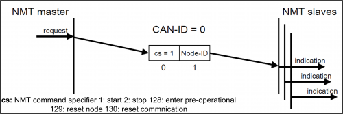
Similar to the PDO protocol, an OpenECU CAN transmit block can be used to implement the NMT protocol as well. Instead of putting process data on CAN message, the command specifier and Node-ID need to be specified as the CAN message data.
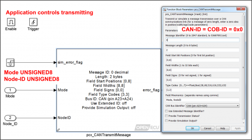
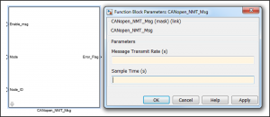
In the reference design model, a masked NMT block is provided from the CANopen library. It gives the interface to enable message transmission, change modes, specify the node ID of the slave device being commanded, and set the node ID, and the rate at which to transmit the message.
CAN DBC Support
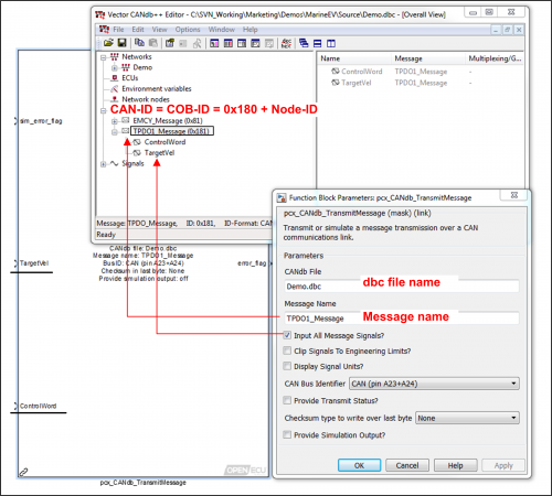
OpenECU also provides CAN blocks that can use a .dbc file to specify the message ID’s and content instead of explicitly defining the message structure of each PDO message. The principle is the same, but these blocks provide access to the information using the textual names assigned in the database, making the model easier to create and maintain.
CANopen Communication State Management
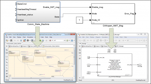
In addition to the CAN blocks used to transmit or receive messages from CANopen slave devices, a communications state manager is required by the CANopen protocol. The reference design model provides a state machine that determines the NMT state which is required by all CANopen devices.
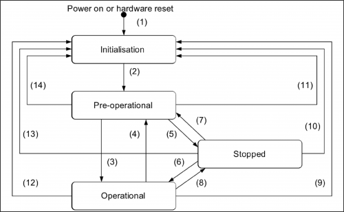
As shown in the figure below the Stateflow chart on the left controls network states according to the requirements of the CiA 301. While the the right side is implementing NMT protocol to transmit NMT data to slave device (Node-ID = 1) with OpenECU CAN block. Another example is application software calculates the target speed velocity and send to slave devices by PDO protocol.
Summary
OpenECU Simulink CAN blockset can implement several CANopen communication protocols without much effort. Pi provides a validated reference design model to demonstrate the methods. More complicated functions, e.g. network management, devices control and diagnostics, etc. can be implemented at application software level using Simulink blocks.
For more information on the CANopen standard please go to https://www.can-cia.org/can-knowledge/canopen/canopen/
