We are pleased to announce a new release of the OpenECU Functional Safety Developer Software. OpenECU FuSa was developed according to ISO 26262 for use on the M560 and M580 targets. For detailed information on functional safety, request the M560 Family Functional Safety Manual.
Users of M560 and M580 ECUs are encouraged to upgrade to this version as soon as possible to take advantage of the new features and fixes therein. Release 3.3.0 includes many new features, fixes and improvements, some of which are briefly described below.
Click here to download – account verification required
Please note that existing customers will need to contact support for an updated license. If you do not have an existing support contract, please contact Dana Novi Technology Center for a quote.
New Support & Features
New features introduced by this version, or significant changes to existing features.
Third party tool support
OpenECU builds on, and utilizes, various tools from third parties, including C compilers, calibration tools and operating systems. See the third party tool requirements section for a complete list of required and options software, and the versions supported.
- Added support for MATLAB R2023a
- Added support for Simulink ASAP2 generator (R2021b and greater)
Communications
External communication mechanisms and protocol support for both reprogramming and application mode, including CCP, SAE-J1939 and ISO-15765 over CAN.
- Added CAN gateway feature to forward messages between CAN buses
- Added ability to change time delay between J1939 BAM packets.
Input/output drivers
Each target ECU is designed with a different set of input and output conditioning circuitry.
- Increased ADC sample time, which can improve accuracy of analog input measurements under some conditions.
Fixes and Improvements
- Removed null termination character from Vehicle-to-Grid (V2G) supportedAppProtocol message strings.
- Fixed false positive errors reported by QCA driver (used for V2G communications)
Learn more on more fixes and improvements in the release note.
Today’s vehicles rely heavily on complex electrical systems to provide advanced features. Although these systems provide many convenience and safety enhancements, they introduce new failure modes which must be addressed by appropriate diagnostics and diagnostic architecture.
The use of electronic parking brakes (EPB) over manual lever-actuated parking brakes imposes new requirements for advanced diagnostics to ensure proper brake operation and the functional safety of the vehicle. The development of an EPB controller by Dana provides insight into several often-underappreciated aspects of diagnostic architectures.
Diagnostics Overview:
The role of diagnostics in any control system is to detect anomalous or undesired operation of a component or components in that system. Diagnostics have an immediate impact on both system availability (ability of a user to perform some task) and functional safety (the absence of unreasonable risk due to hazards caused by malfunction behavior[i]). A diagnostic that detects a fault when one is not present (a false positive) can cause a driver to be unable to perform some task. This may be a nuisance, such as not being able to select a desired channel on the radio, or something more severe rendering the vehicle inoperable. A diagnostic that fails to detect a fault may also result in a hazardous situation. For EPB systems, the most severe fault is a sudden application of braking force when driving at high speed. Failure to detect such a fault has a high probability of resulting in a high-severity, low-controllability situation.
A park brake is often the only retention mechanism for electric powertrains due to the lack of driveline resistance to freewheeling. As such, the combination of the need for availability and functional safety requires balance in the system design and approach to diagnostics. Immobilizing a vehicle is a safe condition in response to faults, but has a dramatic adverse impact on vehicle availability.
Example topology:
For high availability and high functional safety, EPB systems typically employ redundant processing components, which work in concert, providing braking when needed and preventing unintended braking. Figure 1 shows the example control topology used discussed in this paper.
This topology provides detection of and protection against:
- Unintended actuation
The secondary microcontroller can open the low-side path independently of the micro, preventing inadvertent control from the primary. Current-monitoring on both legs can detect shorts to supply, or ground outside the controller.
- Actuation in wrong direction
Both microcontrollers measure voltage on both terminals of the caliper, providing independent, redundant measurement of direction.
This topology provides detection against
- Failure to actuate
Redundant voltage and current measurements can detect failure to actuate due to incorrect command, and due to some failures of gates and external components. Load-off shorts and open can be detected by measuring terminal voltages with zero, or only one high- or low-side, gate active.
Approach to diagnostics
The fault management strategy is as important as the technical details of fault detection and mitigation. A fault management strategy consists of several main concepts:
- The fault life cycle. When to set faults, when to clear faults, and how to report faults.
- Awareness of diagnostic capabilities of hardware components and the relationship to safety analyses.
- Coordination of fault detection, and response among distributed processing components.
Life cycle
The diagnostic life cycle in this paper is defined as the cycle of detecting a fault condition, confirming the fault, then acknowledging a return to the absence of the fault condition.
While the criteria for determining the presence of a fault condition is normally well understood (e.g. detecting current when none is expected, which indicates unintended actuation), the conditions for returning to a fault-absent state are less clear.
The available choices for returning to fault-free behavior fall into one of several broad categories:
- Simple debounce
- Drive-cycle debounce
- Condition-based debounce
- Manual/service recovery
The type-of-fault recovery mechanism must be informed by the functional safety analyses for the system.
Some examples from an EPB system are tabulated below.
| Fault | Fault Recovery Method | Rationale |
| Wrong command to motor | Manual/service recovery | A wrong command to the motors indicates a fault within the microcontrollers or drive circuitry which can only be rectified by controller replacement. |
| Overtemperature and/or transient Current Trips | Simple or condition-based (time) debounce | Temperature and current faults can be due to transient environmental conditions, meaning a retry or delay-and-retry scheme is appropriate. |
| Open / Short circuit detection | Manual/service recovery | Open and short circuits indicate either a failure of drive circuitry or a failure in external components, such as harnesses, which warrant inspection and/or repair. |
Consideration of hardware capabilities
Hardware capabilities of a control module are intrinsic to the diagnostics available on a module. The specific use cases for which a controller is designed, drive the part selection, which has a specific impact on the diagnostics.
EPB controller output drivers are a hardware component of particular interest. Modern output driver chips often have built-in capabilities for detecting, and automatically protecting against, temperature and current excursions. Some chips also include built-in facilities for open- and short-circuit detection with the load commanded on or off. While this can be convenient, it is important to ensure the method of reporting those internal driver states, to the application, is well understood. Some chips, for example, may report a single status bit to the application rather than individual status bits.
EXAMPLE: An H-bridge chip, providing a single bit, indicates a fault but does not disambiguate between overcurrent, over-temperature, or open-/short-circuit. The application software must use multiple sources of information to determine the fault, and then associate an appropriate fault action. In Figure 1 – Example EPB Topology, the independent current measurements outside of the driver chips allowed disambiguation between excessive current, and driver overtempt faults.
Coordination of fault detection and response
The most challenging aspect of managing faults is related to safety mechanisms on the EPB topology. In a topology, as in Figure 1, there are two independent computation units, each capable of independently disabling the outputs. Care must be taken to handle how an intervention by one computation unit is interpreted by the other computation unit.
In a naïve implementation, the primary microcontroller is likely to detect an open-circuit fault if the secondary microcontroller disables the caliper motor. To avoid nuisance faults, the secondary micro must be able to communicate to the primary that it is actively intervening. This may require high-frequency communication, since the fault handling time intervals are short for EPB.
Fault reporting
Once the application has detected a fault, the final aspect of fault management is the reporting concept. There are two scopes of fault reporting: indications to the vehicle operator, and fault reporting for diagnostics and service.
A driver needs to know if a feature is available or not, ideally before needing that feature. A diagnostic that detects potential latent failures should be indicated to the driver as soon as the failure is identified. Generally, drivers only need to know that something will likely not work as expected. The cause is not relevant information to the driver. Additional diagnostic indication should direct the vehicle operator to a course of action, rather than only indicating a fault.
For service tools, much more detailed information is necessary, often including best estimate of root cause to direct repair activities. An internal EPB controller fault should be distinguished from a caliper fault, for example, with a specific fault identifier.
Concluding remarks
A technical consideration alone, of how to detect and address faults in modern vehicle systems, is not sufficient. It requires a holistic approach. The fault detection and management architecture must satisfy the requirements for functional safety, while maintaining reasonable vehicle availability. The fault indication strategy must be able to provide guidance to the vehicle operator, without being distracting or providing non-actionable information.
[i] ISO 26262-1:2018 Clause 3.67
With complex vehicle architectures designed into modern vehicles for ADAS, EV systems, gateways etc., a simple ignition key driven ECU wake up architecture is no longer adequate. New strategies that require ECUs to be woken up by CAN traffic, or on a specific CAN message, are becoming a requirement. For example, EV architectures require a periodic wake-up of the ECU to perform some scheduling and background tasks, even when the vehicle is not in use. This requires a real-time clock wake up functionality in ECUs.
The M560 and M580 families of Functional Safety (ISO 26262) Vehicle Control Units (VCU) take modern vehicle architectures into consideration. They have the following wake sources:
- Wake on RTC clock
- Ignition (Pin XD1)
- Fuel Door Button (Pin ZA2)
- Control Pilot (Pin XF1)
- Wake on CAN bus A Message(s) (Traffic present or Specific Message IDs) (Pins YE4 & YF4)
- Wake on CAN bus B Messages (Traffic present) (Pins YJ4 & YK4)
The Wake_M560_M580_Sleep example Simulink model demonstrates the M560 and M580 ECU’s flexibility to either bring the ECU to a sleep state, or wake it from a sleep state. The Simulink model follows a top down/left right flow, allowing the user to easily follow the logic. Within the Simulink model, the user will be able to identify the following key characteristics of the M560 or M580:
- Selecting the type of Real Time Workshop (RTW) build,
- Configuring CAN/CCP settings,
- Enabling the secondary microcontroller and
- Details about configuring the six wake-sources for the M560 or M580
An easy to use, and easy to build, example Simulink model supporting OpenECU M560 and M580 families of rapid control prototyping embedded controllers is available for download here. It is intended to introduce users to the ease and simplicity of creating, and building, applications using OpenECU.
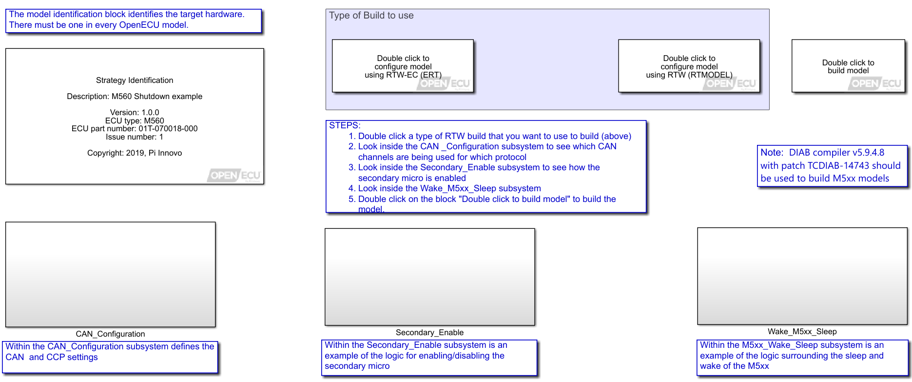
Use cases for testing the wake sources
- Download the Example model: http://support.openecu.com/
- Download the User Guide for Simulink API
- Read the comments in the model to take next steps
A snippet of the instructions for the example model with various wake sources is provided below:
- RTC (Real Time Clock)
- The steps of operation to test this feature are as follows:
- Set slpc_mins_RTCData to a value that you want to wake the M5xx up after it has been asleep (units are in Minutes)
- Verify that slp_b_WakeSourceOff is not true
- To verify which source is holding slp_b_WakeSourceOff False look at the following variables:
- slp_b_XD1Ign (ignition input)
- slp_b_ZA2FuelDoorButton (fuel door button input)
- slp_b_XF1ControlPilot (control pilot input)
- slp_b_canAwaketrg (CAN A wakeup flag)
- slp_b_canBwaketrg (CAN B wakeup flag)
- To verify which source is holding slp_b_WakeSourceOff False look at the following variables:
- Whichever input is true, disconnect that input and verify that slp_b_WakeSourceOff goes true
- Observe that in the time set on slpc_mins_RTCData that the M5xx wakes up and then goes back to sleep
- The steps of operation to test this feature are as follows:
- The steps of operation to test this feature are as follows:
- Set slpc_mins_RTCData to 999 (we do not want to wake the M5xx up after it has been asleep
- Verify that slp_b_WakeSourceOff is not true
- To verify which source is holding slp_b_WakeSourceOff False look at the following variables:
- slp_b_XD1Ign (ignition input)
- slp_b_ZA2FuelDoorButton (fuel door button input)
- slp_b_XF1ControlPilot (control pilot input)
- slp_b_canAwaketrg (CAN A wakeup flag)
- slp_b_canBwaketrg (CAN B wakeup flag)
- To verify which source is holding slp_b_WakeSourceOff False look at the following variables:
- Whichever input is true, disconnect that input and verify that slp_b_WakeSourceOff goes true
- Set pin xD1 true and verify that the variable slp_b_WakeSourceOff goes true and that the M5xx wakes up
- The M5xx will stay awake based on the value set on the calibration variable slpc_s_PsuHoldOffDelay.
- The steps of operation to test this feature are as follows:
- Set slpc_mins_RTCData to 999 (we do not want to wake the M5xx up after it has been asleep
- Verify that slp_b_WakeSourceOff is not true
- To verify which source is holding slp_b_WakeSourceOff False look at the following variables:
- slp_b_XD1Ign (ignition input)
- slp_b_ZA2FuelDoorButton (fuel door button input)
- slp_b_XF1ControlPilot (control pilot input)
- slp_b_canAwaketrg (CAN A wakeup flag)
- slp_b_canBwaketrg (CAN B wakeup flag)
- To verify which source is holding slp_b_WakeSourceOff False look at the following variables:
- Whichever input is true, disconnect that input and verify that slp_b_WakeSourceOff goes true
- Set pin ZA2 true and verify that the variable slp_b_WakeSourceOff goes true and that the M5xx wakes up
- The M5xx will stay awake based on the value set on the calibration variable slpc_s_PsuHoldOffDelay.
- The steps of operation to test this feature are as follows:
- Set slpc_mins_RTCData to 999 (we do not want to wake the M5xx up after it has been asleep
- Verify that slp_b_WakeSourceOff is not true
- To verify which source is holding slp_b_WakeSourceOff False look at the following variables:
- slp_b_XD1Ign (ignition input)
- slp_b_ZA2FuelDoorButton (fuel door button input)
- slp_b_XF1ControlPilot (control pilot input)
- slp_b_canAwaketrg (CAN A wakeup flag)
- slp_b_canBwaketrg (CAN B wakeup flag)
- To verify which source is holding slp_b_WakeSourceOff False look at the following variables:
- Whichever input is true, disconnect that input and verify that slp_b_WakeSourceOff goes true
- Set pin XF1 true and verify that the variable slp_b_WakeSourceOff goes true and that the M5xx wakes up
- The M5xx will stay awake based on the value set on the calibration variable slpc_s_PsuHoldOffDelay.
- The steps of operation to test this feature are as follows:
- Set slpc_mins_RTCData to 999 (we do not want to wake the M5xx up after it has been asleep
- Verify that slp_b_WakeSourceOff is not true
- To verify which source is holding slp_b_WakeSourceOff False look at the following variables:
- slp_b_XD1Ign (ignition input)
- slp_b_ZA2FuelDoorButton (fuel door button input)
- slp_b_XF1ControlPilot (control pilot input)
- slp_b_canAwaketrg (CAN A wakeup flag)
- slp_b_canBwaketrg (CAN B wakeup flag)
- To verify which source is holding slp_b_WakeSourceOff False look at the following variables:
- Whichever input is true, disconnect that input and verify that slp_b_WakeSourceOff goes true
- Transmit CAN Message 512 on CAN Channel A and verify that the variable slp_b_WakeSourceOff goes true and that the M5xx wakes up
- The M5xx will stay awake based on the value set on the calibration variable slpc_s_PsuHoldOffDelay.
- The steps of operation to test this feature are as follows:
- Set slpc_mins_RTCData to 999 (we do not want to wake the M5xx up after it has been asleep
- Verify that slp_b_WakeSourceOff is not true
- To verify which source is holding slp_b_WakeSourceOff False look at the following variables:
- slp_b_XD1Ign (ignition input)
- slp_b_ZA2FuelDoorButton (fuel door button input)
- slp_b_XF1ControlPilot (control pilot input)
- slp_b_canAwaketrg (CAN A wakeup flag)
- slp_b_canBwaketrg (CAN B wakeup flag)
- To verify which source is holding slp_b_WakeSourceOff False look at the following variables:
- Whichever input is true, disconnect that input and verify that slp_b_WakeSourceOff goes true
- Transmit a CAN Message on CAN Channel B and verify that the variable slp_b_WakeSourceOff goes true and that the M5xx wakes up
- The M5xx will stay awake based on the value set on the calibration variable slpc_s_PsuHoldOffDelay.
This article addresses the applicability of CE and E-marks to automotive electronics, when looking to sell automotive electronics systems into Europe, and how Dana OpenECU products can support customer’s regulatory challenges.
What is CE marking and how does it apply to automotive electronics?
According to https://ec.europa.eu/growth/single-market/ce-marking/ the CE marking indicates a product has “been assessed to meet high safety, health, and environmental protection requirements.” These requirements cover a range of products & potential sources of pollution.
Automotive electronics largely fall into categorical exemptions from CE marking. For example, most automotive electronics do not have operating input or output voltages above 50Vac, or 75Vdc, and therefore are not in scope for the Low Voltage Directive 2014/35/EU. CE marking also includes an EMC directive, 2014/30/EU, which includes a categorical exemption for vehicles/automotive electronics on the basis that there is a more specific directive for the automotive industry.
What is E-marking and how does it apply do automotive electronics?
According to https://www.unece.org/trans/main/wp29/wp29regs0-20.html E-marking is a regulatory process for vehicles, and electronic sub-assemblies, which certifies the product demonstrates a bare minimum of EMC immunity for safety functions, and has EMC emissions below a statutory maximum. Tests on electronic sub-assemblies also check for immunity against transient disturbances common in automotive electrical systems. The level of formality associated with E-marking is significant. Testing related to E-marking must be witnessed by a regulatory body, at a certified lab, to a pre-approved test plan. That testing rigor differs from CE mark requirements, which often simply require a self-certification.
E-marking is the automotive industry specific EMC process which supplants the CE EMC directive according to 2014/30/EU Article 2(3). It is required for all vehicles sold in Europe.
There are two paths available to achieving E-mark, at the discretion of the manufacturer:
- E-marking can be achieved by testing the vehicle as a whole
- E-marking can be achieved by testing each electrical sub-assembly (ESA) and integrating them within their installation guidelines
Both paths require a test plan approved, and testing observed by a notified body. The test plan must identify:
- the immunity related functions (of the ESA or vehicle) related to:
- control of the vehicle
- signaling other road users
- vehicle occupant and road user protection
- the mission profile, and load simulators, which are expected to produce the max EMC emissions
E-mark testing is similar to typical OEM-specified EMC testing, althoughgenerally, the limits of the tests are less stringent than common OEM specifications:
- Radiated emissions (CISPR 12 & 25)
- Radiated immunity (ISO 11451 & ISO 11452)
- Power line transient immunity & emissions (ISO 7637)
How Dana can help customers achieve E-marking and regulatory compliance
Dana helps customers plan for, and execute, E-mark testing on custom controller products and systems containing an OpenECU controller, based on the knowledge gained from pre-compliance testing. All OpenECU products have undergone pre-compliance testing, covering the same test types required for E-marking. The remining system information needed to develop a test plan are:
- The immunity related functions
- Dana can use its safety expertise and Functional Safety Certified Automotive Engineers to define those functions for a customer’s system
- The loads and mission profiles that produce maximum emissions
- Dana can use its 30+ years of automotive electronics design expertise to assist customers in defining these profiles
Dana has experience integrating its OpenECU controllers into systems that have achieved regulatory compliance, and can offer flexible support models to assist customers at every stage, from development and validation, through volume production.
Formula SAE Team from the University of Michigan:
Michigan Electric Racing (MER) uses Dana’s M220 and M110 OpenECU controllers for Formula SAE Electric Vehicle.About Formula SAE:
“SAE International’s Collegiate Design Series (CDS) competitions take students beyond textbook theory by enabling them to design, build, and test the performance of a real vehicle and then compete with other students from around the globe in exciting and intense competitions.”- SAE.Michigan Electric Racing designs and builds an all-electric formula style race car every year. MER vehicles include many cutting-edge features:
- Independent, Dual Rear Wheel Drive
- Custom Battery Pack, designed from the cell up
- Custom Distributed Battery Management System
- Custom Motor Controllers
- Independent Torque Vectoring and Traction Control
- Live Data of three interoperable vehicle CAN Buses
- Full Aerodynamics Package, including front/rear wings, Undertrays, Diffuser, Side Wings, and Complete Body Work
- Rear Wheel Bump Steering
- Custom, In-House Manufactured Gearboxes, Spindles/Uprights, and other Suspension Components
- Advanced Driver Interface Controls and Feedback
Learn More about the team here
PLC Tuning
Power-Line Communication (PLC) is used during charging of electric vehicles around the world and is a must-have in today’s electric vehicle (EV) market. PLC allows the charging station (aka electric vehicle supply equipment or EVSE) and the EV to negotiate charging sessions, allowing various charging profiles and potentially to negotiate payment. Dana’s M560 and M580 modules have PLC capability built in.
Power-Line Communication (PLC) as depicted in ISO 15118-3 and DIN 70121 specifies power spectral density (PSD) limits of the HomePlug Green PHY PLC signal injection on the Control Pilot line for vehicle charging. HomePlug Green PHY is the standard for PLC signals used in vehicle charging called out in ISO 15118. Attenuation levels specified in the standards allow the differentiation between PLC signals on a connected charging station from crosstalk with a neighboring charging station. Higher than specified PSD on the PLC signal could cause disturbances in the Control Pilot detection, while having a signal too low could be interpreted as crosstalk or cause packet loss during the charging session. Having proper tuning provides the best environment for ensuring proper connection between a charging station and the electric vehicle.
Every vehicle model will have differences in mounting location and wiring harnesses for the charge controller module, which causes the attenuation on the Control Pilot line to vary. These differences may affect the entire spectrum of frequencies used for PLC, or only a subset. The default configuration of Dana’s modules will work in almost every situation, but with the different harness designs, there is the possibility of not meeting the DIN and ISO standards. Tuning, therefore, is essential for each vehicle model and Dana has the expertise on the tuning process of our M560 and M580 modules for use in our customer’s vehicle.
The maximum PSD of the PLC signal at the electric vehicle socket is -73dBm/Hz, with the target being -75dBm/Hz, as specified in ISO 15118-3. Dana can take measurements and, using some proprietary software, modify the PSD across the frequency spectrum to bring the entire PLC frequency band into compliance. Here is an example of a measurement taken on a pre-tuned and post-tuned module. Note that there are some frequencies with very low values, which are notched frequencies called out in the ISO and DIN standards. Additionally, note that the dBm value targeted is about -35dBm because with the resolution bandwidth used, the dBm/Hz ends up at the target of -75dBm/Hz.
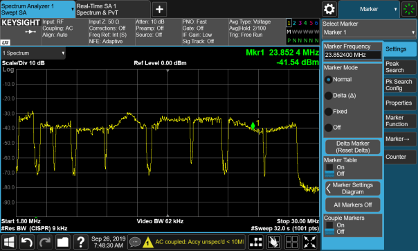
Figure 1 Module Before Tuning
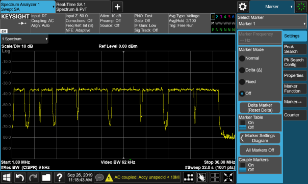
Figure 2 Module After Tuning
Once Dana creates an updated configuration for the customer’s vehicle, that configuration is used to program modules during production, eliminating the need for the customer to be concerned with having the correct configuration on the module. This configuration is not saved in the same memory as the application space, so the customer can continue to develop their vehicle application as usual.
Summary
- The OpenECU BMU is a rapid control prototyping embedded controller for Battery Management System (BMS).
- Provides control of the battery pack contactors and monitoring of the pack voltages and current
- Supports isoSPI cell monitoring unit (CMU) slaves selected by customer to provide a complete battery management solution
- Supports customers to develop BMS application using OpenECU Simulink or C API
- Hardware comprises of low voltage section and high voltage section.
Performance
- A dual microcontroller architecture providing redundancy with a main controller for control and secondary microcontroller for safety monitoring of the operations
- Designed to measure voltages in excess of 50V up to 1000V
- Includes the LTC2949 High Voltage Pack Monitor providing 8 channels capable of measuring 1000V
- Two current shunt inputs to calculate charge, energy and power flow into and out of the pack
Capable
- OpenECU, Dana’s base software (BSW) provides developers with Simulink® or C API for application development
- High-quality rugged hardware design for Battery Electric Vehicles and Hybrid Electric Vehicles
- Supports common calibration tools such as ATI Vision, ETAS INCA, and Vector CANape via CCP as well as Dana calibration tool OpenECU Calibrator
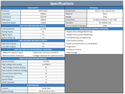
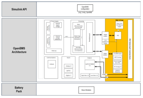
Dana’s BMU Master Controller is a rapid control prototyping embedded controller for Battery Management Systems. BMU Master Controller adopts isoSPI for communication with cell monitoring slaves. BMU Master Controller combines low voltage and high voltage in a single ECU providing cost optimized solution for our customers.

Dana has been a Kvaser Technical Associate (TA) and Qualified Sales Representative (QSR) for a number of years, and enjoys a good working relationship with this titan of the CAN (Controller Area Network) world! More than just using Kvaser CAN interface products as part of delivering embedded control solutions in development and in the production environment, we value Kvaser’s insights into the application of CAN in the transportation industries.
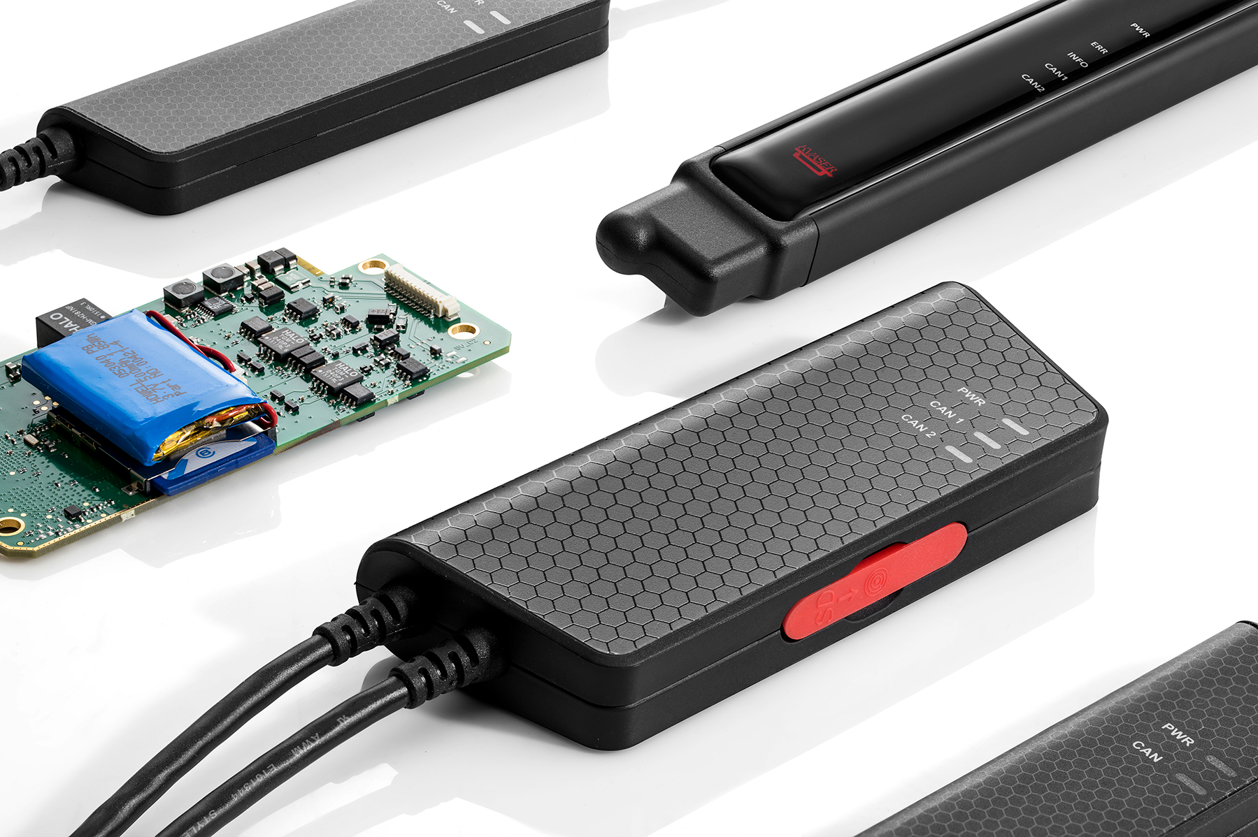
Being involved as part of the Kvaser TA network has been a valuable experience, bringing awareness of new developments in the CAN world, for example the introduction of CAN-FD, which offers the ability to access higher bandwidth and data rates. Another benefit that the relationship has afforded us is the opportunity to network with other TA organizations, with the chance to forge new business relationships, and to have some fun doing so as part or the regular TA meetings that the Kvaser team organizes.
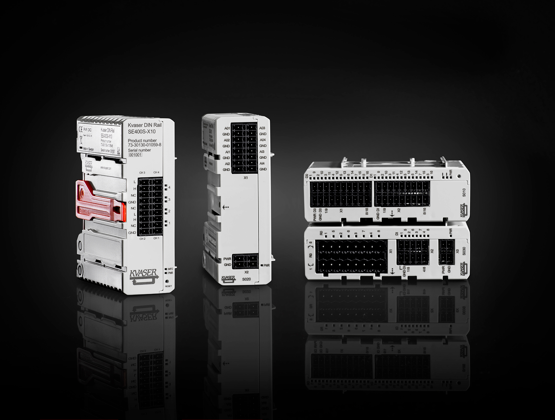
A good recent example of Dana’s collaboration with Kvaser was demonstrated during the EV Tech Expo in Novi, MI, where Kvaser’s Bryan Hennessy worked with Dana’s Amir Rezaei to showcase the capabilities of the OpenECU M560 controller running our CCS (Combined Charging System) base software and application strategies by simulating an EVSE (Electric Vehicle Supply Equipment) unit using Kvaser’s DIN rail product. More information about this effort was recently posted on the Kvaser website here: https://www.kvaser.com/simulating-an-electric-vehicle-charging-station-battery-show-demo-walkthrough/
DV BMU Emissions Test Issues
During development of our Battery Management Unit (BMU) we performed DV testing and found an issue in the radiated emissions test. Our schedule to meet the customers deadlines was tight so we did not perform pre-DV emissions scans which would have caught this failure earlier. We had to find a solution quickly to keep the BMU project on schedule so we needed to narrow down the root cause of the emissions failure, find a workable solution and test a prototype fix all within < two weeks? >.

Figure 1 – BMU measured emissions (Peak, QP and Average) and corresponding limits
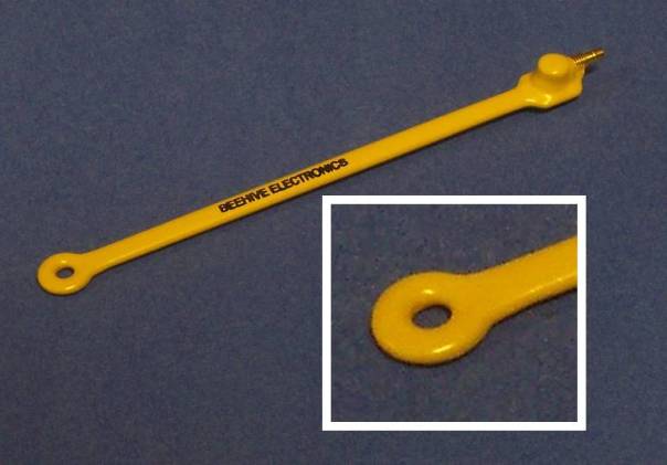 We quickly found the root cause of the emissions issue; using a near field magnetic field probe along with OpenECU’s spectrum analyzer our engineers found that the emitted noise was due to the SPI isolator integrated circuit (IC). That IC transfers the serial peripheral interface (SPI) signals and DC power from the 12V vehicle side of the BMU to the high voltage battery side for acquisition of the high voltage measurements such as the battery stack voltage. This device has internal transformers which transfer the power and signals across a 2500V isolation barrier. This requires high frequency switching to provide high efficiencies in the transformers. Switching noise internal to this part was being inserted into the high voltage side of our module and radiating out into the environment.
Dana engineers worked with the manufacturer of the isolator IC, Analog Devices Incorporated (ADI), to investigate the source of its noise. ADI engineers developed a reference design for this part that could pass automotive emissions tests but had found similar issues during their initial reference design work.
ADI engineers found that a capacitive current path was required to bypass the high frequency noise of the isolated DC/DC convertor back from the high voltage side of the board to the low voltage side. Also, filtering was required between the 5-volt isolated output of the device to the devices it powers on the high voltage side. ADI engineers recommended extending copper internal to the circuit board across the isolation barrier to provide an overlapping capacitive path. Our customer did not want to us to implement this approach because their research had indicated the possibility of breakdown of the isolation material in the printed circuit board over long-term use. Dana engineers modified a board to add high voltage rated capacitors across the isolation barrier along with filtering of the power output from the device.
Retesting the module for emissions indicated that these changes had reduced the noise below the acceptance levels of the test. Unfortunately, the re-test found that now the module was failing the test for susceptibility to the external noise. Dana engineers investigated this and realized that when the filtering to the power supply was added, the output impedance was increased to the point that the bypassing capacitance on the high voltage measurement parts was inadequate to overcome the injected noise a certain frequencies. Dana engineers calculated what capacitance was required, added the capacitors to the modified module and went back for another day of testing. This round the module passed the tests. A design with these modifications was ready for release with hours to spare before causing a schedule slip for the customer.

Dana recommends a project schedule includes a suite of pre-design verification tests which can be done at a reduced cost in time and money in development schedules. In this project these tests were not planned in order to meet an aggressive schedule and issues that the pre-DV testing would have found were not found until the DV testing. Fortunately, Dana engineers were able to find the source of the problem and a solution without causing a slip in the project schedule.