
The process for doing this verification is called Design Verification (DV).
DV has multiple steps which are documented in a Design Verification Plan and Report (DVP&R) for testing of the design, and in analysis reports. These are
- Analysis and calculations
- The plan for the design verification testing
- The testing
- The report documenting the design verification testing
For safety related designs Dana follows ISO-26262 processes which drive the analysis and testing from tables that define the level of rigor for the different automotive safety integrity levels (ASIL). The ISO 26262 tables determine the safety related analysis and requirements for the design verification. For non-safety related designs Dana uses a less rigorous process with many steps shared with the ISO-26262 process.
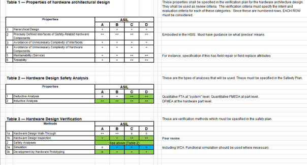
As the Table 1 above shows, design failure mode effects analysis (DFMEA) is an inductive method used to analyze what the effects of a failure would be and what could cause those failures. DFMEA drives how to determine what components and subsystems require special attention in testing to determine the system will be robust enough to meet the requirements. The DFMEA process is used in most Dana projects.
For higher safety designs (ASIL-C and above) Dana also uses deductive analysis such as fault tree analysis (FTA) and quantitative failure modes, effects and diagnostic analysis (FMEDA).
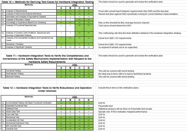
Once the customer requirements and safety requirements driven from ISO 26262 Tables 1-3 in the figure above, are determine the requirements for testing and analysis are developed. ISO 26262 tables 10-12 below show how these requirements are determined for safety related projects. verification.
This development of project and safety requirements drives the DV Plan
Analysis
The analysis step of DV verifies that the design meets the safety and project requirements along with determining what additional test may be required. As can be seen in ISO26262 tables above this includes:
FTA – Fault tree analysis is a deductive method to determine what faults could happened and what lower level events could lead to those faults.
FMEDA – The failure modes, effects, and diagnostic analysis (FMEDA) is an inductive, systematic analysis technique to obtain subsystem / product level failure rates, failure modes and diagnostic capability.
The FMEDA technique considers:
- All components of a design
- The functionality of each component
- The failure modes of each component
- The effect of each component failure mode on the product functionality
- The ability of any automatic diagnostics to detect the failure
- The design strength (de-rating, safety factors)
- The operational profile (environmental stress factors)
Given a component database calibrated with field failure data that is reasonably accurate [1] , the method can predict product level failure rate and failure mode data for a given application. The predictions have been shown to be more accurate [2] than field warranty return analysis or even typical field failure analysis given that these methods depend on reports that typically do not have sufficient detail information in failure records.[3]
WCA – The worst case analysis calculates whether the components in the design will be within the specified working range during the worst case conditions the unit will experience . Dana uses SMath Studio for much of this analysis with support from Excel spreadsheets and circuit simulations using SPICE.
DFA – The dependent failure analysis identifies possible common cause and cascading failures between parts in the design. This includes assessment of risk of violating a safety goal and the safety measures to mitigate such risk if necessary.
DV Plan
Once the design and safety requirements are fully determined the first step of DV is developing the design verification plan (DVP) f rom the design and safety requirements. The DVP includes acceptance criteria for the tests to show that the design meets the requirements. This acceptance criteria is usually included in the test specifications called out by a customer or industry standard.
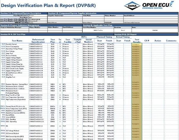
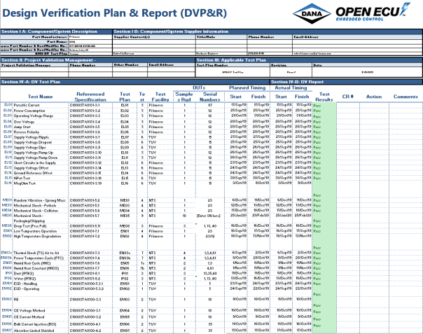
The DV plan documents the timing and requirements for the DV testing including what tests will be performed, the order they will be performed in. The plan includes the following:
- Test number – An identification number for tracking the test
- Test Name – A descriptive name for the test
- Specification – The specification for how the test is run. This may be from the customer or it may be an international standard such as ISO-16750
- Test Leg – often units are tested through sequential series of test with each leg in parallel
- Test Facility – The location where the test will be done. This may be at Dana or one of the testing house Dana uses such as TUV SUD America, or NTS Detroit
- Samples Require – this is the number of units to be tested in the specific test.
- Serial Numbers – the serial numbers of the units to be tested
- Planned Start – the date the test is planned so start
- Planned End – the date the test is planned to end
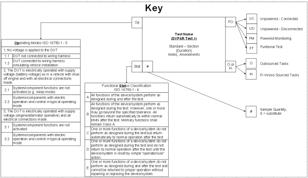
Dana documents flow of testing showing the number of units and what sequence the tests are to be performed in a chart like below:
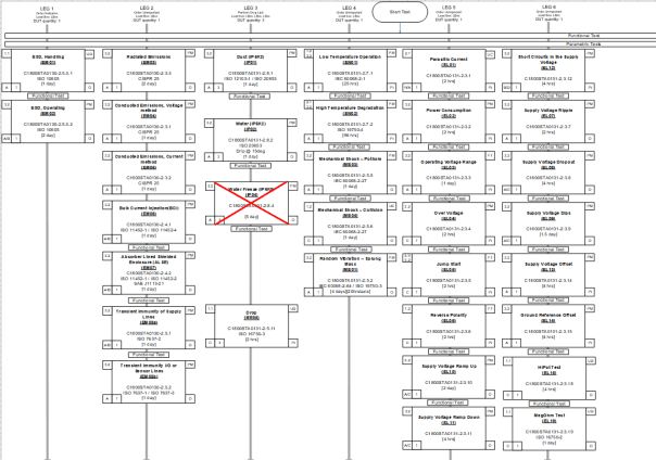
The individual blocks describe what the test is, the operating mode of the device, the functional classification of the unit during the test and whether the unit is tested at Dana or at and outside vender. The key for these blocks is shown below
Testing
Once the DVP is approved and the specimens to be used for the DV testing have been produced the testing proceeds. As can be seen in the Test Facility column (highlight column above) this testing may occur at Dana, or at a testing facility contracted by Dana. The testing for design verification often includes the following types of tests depending on the nature of the project:
| Parasitic Current | MegOhm HV Isolation Test |
| Power Consumption | Random Vibration – Sprung Mass |
| Operating Voltage Range | Mechanical Shock – Pothole |
| Over Voltage | Mechanical Shock – Collision |
| Jump Start | Low Temperature Operation |
| Reverse Polarity | High Temperature Degradation |
| Supply Voltage Ripple | Electrostatic Discharge During Handling |
| Supply Voltage Dropout | Electrostatic Discharge While Operating |
| Supply Voltage Dips | Radiated Electrical Emission |
| Supply Voltage Ramp Up | Conducted Electrical Emissions – Voltage Method |
| Supply Voltage Ramp Down | Conducted Electrical Emissions – Current Method |
| Short Circuits in the Supply | Bulk Current Injection (BCI) |
| Supply Voltage Offset | Absorber Linded Shielded Enclosure (ALSE) |
| Ground Reference Offset | Transient Immunity – Supply Lines |
| HiPot Test | Transient Immunity – I/O & Sensor Lines |
International Standard tests
ISO 16750-2:2003, Road vehicles — Environmental conditions and testing for electrical and electronic
equipment — Part 2: Electrical loads
ISO 16750-3:2003, Road vehicles — Environmental conditions and testing for electrical and electronic
equipment — Part 3: Mechanical loads
ISO 16750-4:2003, Road vehicles — Environmental conditions and testing for electrical and electronic
equipment — Part 4: Climatic loads
ISO 16750-5:2003, Road vehicles — Environmental conditions and testing for electrical and electronic
equipment — Part 5: Chemical loads
DIN 40050-9, Road vehicles — Degrees of protection (IP-code) — Protection against foreign objects, water and contact — Electrical equipment
IEC 60068 – Environmental Testing
IEC 61000 – Electromagnetic Compatibility
Millitary standard tests
| 500.4 Low Pressure (Altitude) | 512.4 Immersion |
| 501.4 High Temperature | 513.5 Acceleration |
| 502.4 Low Temperature | 514.5 Vibration |
| 503.4 Temperature Shock | 515.5 Acoustic Noise |
| 504 Contamination by Fluids | 516.5 Shock |
| 505.4 Solar Radiation (Sunshine) | 517 Pyroshock |
| 506.4 Rain | 518 Acidic Atmosphere |
| 507.4 Humidity | 519.5 Gunfire |
| 508.5 Fungus | 520.2 Temperature, Humidity, Vibration, and Altitude |
| 509.4 Salt Fog | 521.2 Icing/Freezing Rain |
| 510.4 Sand and Dust | 522 Ballistic Shock |
| 511.4 Explosive Atmosphere | 523.2 Vibro-Acoustic/Temperature |
General Motors Standard Tests
| GMW3172 | GMW3091 |
| GMW3097 | GMW3103 |
BMW
| GS 95002 |
Daimler
| MBN 10284 |
These tests stress the design to reveal deficiencies that cause the design to not meet requirements or cause premature failures. Discovery during DV allows these deficiencies to be addressed before the design goes to production.
Report
The last step of DV is writing the report which documents and tests were performed on which units and the results of the tests. The report typically will also include comments documenting any issues found, such as non-compliances, and what actions were taken or are planned to address the issues. The DV report provides a clear picture of the status of the DV that is understandable by all stakeholders including management, the customer and team members. It also provides clear documentation of the design testing if issues arise later in the product life.
 Accessibility