Written by Gordan Jurasek, Director of Hardware Advanced Solutions, Dana
Evaluating the suitability of an OpenECU Electronic Control Unit (ECU) for use in your system as an embedded controller is best done in layers with the obvious and superficial screens done first to narrow the candidate pool to a limited quantity followed by the fine detailed requirements test on the narrower candidate pool. Many times, an off-the-shelf module will meet the requirements but for cases where customization is needed, OpenECU is designed to accommodate a wide range of options. The topics in this OpenECU evaluation series are:
- I/O
- Customization
- Mechanical Interfaces (vibration, thermal, mounting) & Usage Profiles of an Application
- Diagnostic Needs and Functional Safety
- Business Needs of the Program
- Design Verification Requirements
- Computational Needs of the Control Strategy
- Development Environment and Library Resources
How to Determine Which OpenECU is Suitable for My System: I/O
The first step in determining which OpenECU Electronic Control Unit (ECU) is most suitable is a simple matching of I/O capabilities to needs.
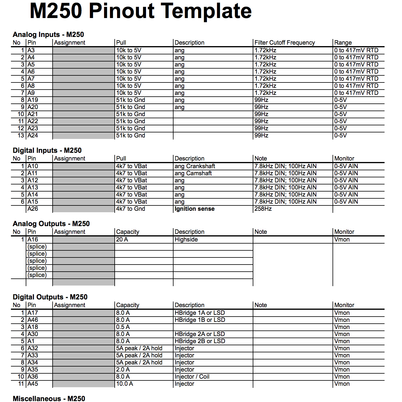
The tools I use daily to evaluate our ECUs for customer applications are the Pinout Templates for our line of OpenECUs. You can have a look at them on the Dana Downloads Page.

The information needed to properly evaluate a match between an application and an OpenECU is the following from the perspective of each ECU pin:
Analog sensor inputs:
- Does the sensor signal need a pull up to 5V or a pull down to ground in the ECU or does the sensor have a true voltage output which requires a high resistance input on the ECU?
- If it needs a resistance pull-up/down, what resistance value?
Digital switch inputs:
- Is the switch open/closed to ground or to battery?
Frequency/duty cycle inputs:
- Does the sensor signal need a pull up? If so, to 5V or to battery and what resistance value or maximum current?
- What is the maximum signal frequency?
Specialty inputs:
- Crankshaft/Camshaft, Wideband Oxygen sensor, thermocouples, knock, etc…
Outputs:
- Does the actuator require the ECU connect it to battery or to ground to turn the actuator on?
- What current does the actuator use when on?
- What is the maximum inrush current or stall current?
- Do the low side driven actuators need battery sourced from a high side switch output of the ECU?
- If the actuator requires a pulse width modulation (PWM) of the output:
- What frequency is the signal?
- What is the inductance of the actuator?
- Does the actuator require an H-bridge output?
- At what current?
- What frequency PWM? (or possibly DC only)
- Does the actuator require some specialty drive or waveform (i.e. 3-phase BLDC, Peak-and-Hold, Current mode control, other?)
- Do the outputs need to be synchronized with an input? (this can be simple pass thru trigger or complex synch like engine angle which is a derived clock from crankshaft and camshaft inputs)
Sensor supply and 5V reference:
- What is the sum of the sensor 5V power requirements in mA? (This number is typically 5-10mA per sensor, although some sensors do consume more.)
- Does your system require redundant 5V supplies?
Serial bus communication:
- What serial communication standards are used in your application? (CAN 2.0b, LIN, Ethernet, CAN-FD, J1939, SENT (SAE J2716), etc…)
- How many of each type are needed?
- Is wake-on-CAN required?
What are the power modes of the ECU:
- Connection to a switched battery supply which is only “hot on run”?
- Direct connection to system battery which is hot all the time with a separate “hot on run” signal used as ignition?
- Direct connection to system battery which is hot all the time with expectation that serial bus communication is used to wake the ECU?
- Sleep with periodic wake from internal RTC?