An engine misfire can be defined as a combustion event where the air fuel mixture within a cylinder fails to ignite properly. The most common causes of misfire are:
- Incorrect air/fuel ratio, generally caused by a lean mixture
- Weak/missing spark due to wear of ignition system components
- Mechanical damage to the engine such as leaking gaskets, piston rings, etc, causing a loss in compression
Misfire has a number of undesirable effects, including
- Loss of power
- Increased fuel consumption
- Increased hydrocarbon emissions from the unburnt fuel
- Catalytic converter damage
Misfire and OBD-II
OBD-II regulations mandate the detection of misfire on all passenger vehicles. In most applications, the Engine Control Module keeps a count of the number of misfire events that occur over a moving window of engine revolutions. If the misfire count exceeds a threshold, a diagnostic trouble code is set.
Misfire Detection Using OpenECU
There are several ways to detect misfire. In this post, we will discuss misfire detection using the crankshaft position sensor. During a normal combustion event, the piston speed is lowest at top dead center on the compression stroke, and is the highest with the piston moving downwards during the power stroke. The average engine speed for a single engine revolution would lie in between the lowest and the highest instantaneous values. The difference between the lowest and highest engine speeds is significant enough that any deviation from the values expected during normal combustion can be used to detect a misfire event. If misfire occurs, the crank speed during the power stroke will be significantly lower as there is no downward force being applied on the piston head from combustion of the air fuel mixture. Figure 1 shows how the variation of instantaneous engine speed with crank angle for normal combustion and misfire conditions.
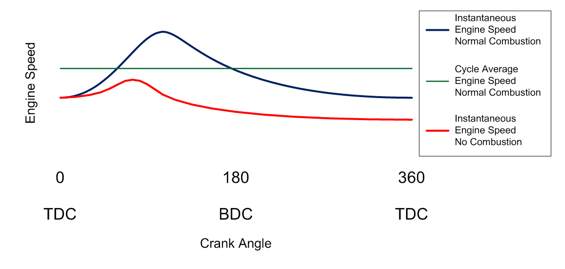
Figure 1 – Instantaneous engine speeds vs crank angle for normal combustion and misfire
The OpenECU Simulink blockset provides an easy way to calculate the engine speed during specific portions of the engine cycle using the crankshaft position sensor. In the example shown in Figure 2, each instance of the Engine Speed block is used to calculate the average engine speed over a different portion of the engine cycle. The first block gives the average engine speed over 720 degrees of crank rotation. The second block calculates the “post-TDC” or highest crank speed and the third calculates the “pre-TDC” or slowest crank speed during the engine cycle. The tooth range is calibratable, which means that it can be easily adjusted in real-time to account for varying operating conditions, such as a change in the spark timing, which can affect the location of the fastest crank speed relative to the TDC of the cylinder.
The tooth ranges can be specified relative to the TDC of each cylinder, or relative to the missing tooth region of the crankshaft position sensor pickup wheel. Each cylinder will have its own pair of blocks to detect the maximum and minimum crank speeds. The speeds calculated by the OpenECU blocks can then be compared and a misfire event can be detected if the separation between the two indicates that the crankshaft did not accelerate during the power stroke.
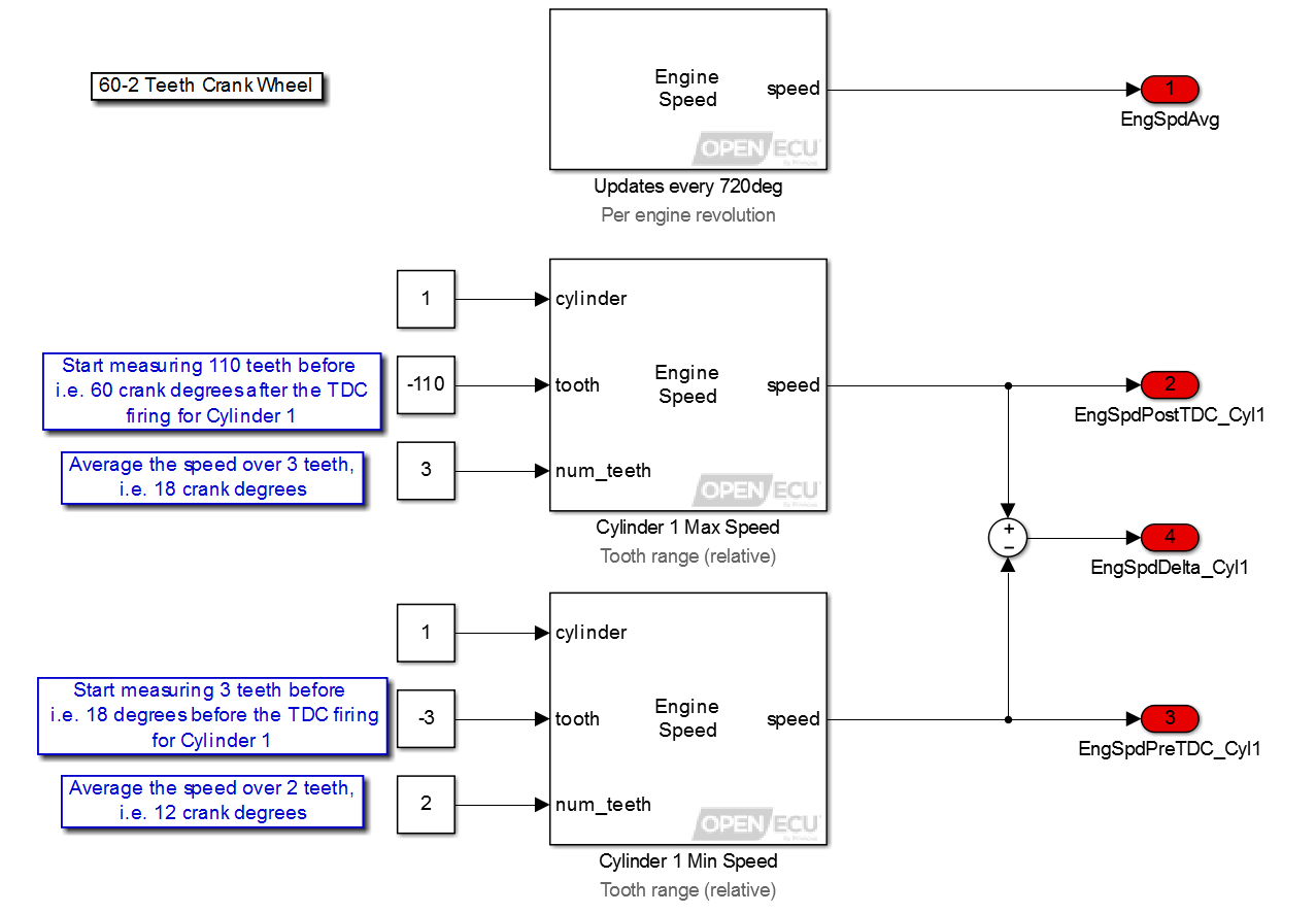
Figure 2 – Example implementation of TDC relative engine speed measurement with OpenECU
The figure below shows the pre and post TDC engine speeds when misfire events are induced on a single cylinder engine using an ignition cut. The reduced difference between the pre and post TDC engine speeds clearly shows the misfire events.

Figure 3 – Pre and Post TDC engine speeds during normal combustion and misfire
 Accessibility