DBC File Support
DBC files are widely used to define the system of CAN messages and their constituent signals. This allows CAN data to be accessed in terms of human-usable signal values, with different data types and scalings, instead of just raw message bytes.
The DBC format is proprietary to Vector Informatik GmbH. To create your own DBC file you must use their CANdb++ tool or some alternative, or obtain a ready-made DBC file for your project from its owner.
This program can use DBC files to show named messages and individual signals in CAN Monitor, CAN Sender and Watch windows.
DBC Setup Window
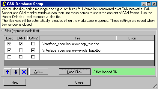
The list of DBC files to load, if any is saved as part of the workspace. To change
it, do File… CAN Database Setup (Ctrl-B), or click the ‘DBC Setup’ button in a
CAN Sender window.

You can choose which CAN channel(s) are associated with which DBC file, so that only messages relevant to each bus are displayed or offered when used.
The chosen DBC files are automatically reloaded when the workspace is opened. These settings are also retained when this window is closed.
You may edit a DBC file outside of the program and press Load Files again. All windows will be automatically updated to take account of any new or altered definitions.
Multiplexed Signals
Some projects use CAN messages with overlapping signal definitions. The “version”of the message is indicated by a multiplex index signal (multiplexor). Different versions of the message are then sent in turn, cycling through the different index values. For example, byte 2 of a message may be a front-right wheelspeed in one transmission, and a back-left wheelspeed in the next.
OpenECU Calibrator supports the automatic handling of these multiplexed signals both in transmission and reception, so long as they are defined in a DBC file. See AutoMux help for automatic cyclic transmission.
Currently, a special version of Vector’s CANdb++ tool is required to define multiplex signals. Alternatively, a simple .dbc file may be edited by hand to create the required definitions. In the example below, three temperature signals are multiplexed into the same location in one message, as follows:
- the red capital M defines the special multiplexor signal which defines the “version” of the message;
- the small red m3 defines that the signal
TemperatureOutdoorsMultiplexedis only to be used whenMultiplexIndexSignalhas value 3; - when transmitting, the sender should cycle through all of the index values used (0, 3, 11), filling the overlapped signal location with the appropriate data at each send.
- Normally consecutive index values are used, but this example shows that non-consecutive values are supported.
 BO_ 1845 TemperatureMsg: 8 Vector__XXX
  SG_ MultiplexIndexSignal M : 39|4@0+ (1,0) [0|0] "" Vector__XXX
  SG_ NormalSignalAlwaysPresent : 16|4@1- (1,0) [0|0] "" Vector__XXX
  SG_ TemperatureIndoorsMultiplexed m0 : 7|16@0- (0.1,-40) [0|0] "degC" Vector__XXX
  SG_ TemperatureOutdoorsMultiplexed m3 : 7|16@0- (0.1,-40) [0|0] "degC" Vector__XXX
  SG_ TemperatureUndergroundMultiplexed m11 : 7|16@0- (0.1,-40) [0|0] "degC" Vector__XXX