
OVERVIEW
Introducing CCU
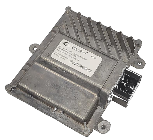
The CCU is an OpenECU™ Charge Control Unit designed as a standalone EVCC for xEV hybrid and battery electric powertrains, including battery electric and plug-in hybrid vehicles. It provides a compact, dedicated charge controller for vehicles that already have a supervisory ECU or need a drop-in CCS charging solution.
The CCU includes onboard DC fast-charging PLC communication according to ISO 15118 and supports ISO 15118-2 CCS, ISO 15118-20, DIN 70121, and SAE J1772. It is designed to meet ISO 26262 up to ASIL-B functional safety requirements and is developed according to ISO 21434 with integrated HSM support for cybersecurity requirements.
Features
- Standalone EVCC for xEV hybrid and battery electric powertrains
- Drop-in DC fast charging with CCS and PLC communication per ISO 15118
- Designed to meet ISO 26262 up to ASIL-B functional safety requirements
- Developed according to ISO 21434 with integrated HSM support
- 36-pin connector with flexible I/O
- Powerful Infineon Aurix TC387 microcontroller
- 2x CAN-FD external communication
- OpenECU Simulink and C-code development environments available
- Supports custom application software written by customers
- Power inlet I/O including PP signaling, lock actuator H-bridge output, lock position feedback input, and 3x PT1000 inputs
- 3x high-side LED outputs
- Comprehensive fault diagnosis supporting functional safety and OBD requirements
- IP69K sealed aluminum chassis-mount design
Core Offering
- EVCC: Standalone electric vehicle charge controller for xEV applications
- Charging: CCS charging with PLC communication according to ISO 15118
- Protocols: ISO 15118-2 CCS, ISO 15118-20, DIN 70121, and SAE J1772
- Cybersecurity: Integrated HSM support and development according to ISO 21434
- Functional Safety: Designed to meet ISO 26262 up to ASIL-B
- Communications: 2x CAN-FD
- Calibration: Supports OpenECU Calibrator™, ATI Vision, and Vector CANape via CCP
- Diagnostics: Comprehensive fault diagnosis supporting functional safety and OBD requirements
Off the Shelf Options
- CCU – Charge Control Unit: Compact standalone EVCC with ISO 15118 PLC onboard for vehicles requiring dedicated CCS charging control.
Hardware Specifications
| Capabilities | |
| Feature | CCU |
| Processor | Infineon Aurix TC387 |
| Clock Rate | 300 MHz |
| Operating Voltage | 9 – 32V |
| Connector | Molex 36-pin |
| External Communication | 2x CAN-FD |
| Protocols | ISO 15118, DIN 70121, SAE J1772 |
| Code Space | Up to 3MB |
| RAM Space | Up to 672kB |
| Calibration Space | Up to 512kB |
| Sensor Supplies | 1x 5V @ 250mA |
| Input Pins | 9 |
| Output Pins | 21 |
| Digital Inputs | Up to 3x |
| Analog Inputs | 6x including 3x PT1000 |
| H-Bridge Outputs | 1x 5A PWM with current feedback |
| Low-Side Drive Outputs | 2x |
| High-Side Drive Outputs | 5x 20mA |
| Partial Networking | 2x Wake on CAN |
| Wake Input | Dedicated ignition wake input |
| Charging Interface | Proximity and Command Pilot pins with PLC communication and wake-on-plugin |
| Dimensions | 163 x 160 x 40mm |
| Material | Aluminum |
| Weight | 570g |
| Location | Chassis mount |
| Vibration | ISO 16750 chassis mount |
| Environmental Protection | -40° to +80°C ambient; IP69K sealed / Gore vent |
APPLICATIONS
CCU Applications Include:
| Application | Description |
| Standalone EV Charge Control | Dedicated EVCC solution for vehicles that already have a supervisory ECU and need compact charging control. |
| Drop-in CCS Charging | Adds modern DC fast-charging capability to existing vehicle platforms using CCS and PLC communication per ISO 15118. |
| xEV Charging Applications | Designed for hybrid, plug-in hybrid, and battery electric powertrains requiring reliable onboard charge control. |
| Commercial and Off-Highway EV Platforms | Rugged chassis-mount hardware suited for light, commercial, and off-highway electric vehicle applications. |
MODULE COMPARISON
Compare ALL OpenECU Modules
Scroll to view full table
| M110 | M130 | M6 Family | M670 | Actuation | M560 | M580 | NX3 | CCU | DLC-12 | ||||||||||||
| Microprocessor | |||||||||||||||||||||
| Primary Processor | SPC5534 | SPC5746B | MPC5534 | MPC5674F | MPC5746B | SPC5746 | SPC5746 | Infineon Aurix | Infineon Aurix TC387 | Infineon Aurix TC364 | |||||||||||
| Primary Clock Rate | 80MHz | 80MHz | 80MHz | 264MHz | 160MHz | 160MHz | 160MHz | 300MHz | 300MHz | ||||||||||||
| Primary Code Space | 512KB | 3MB | 512KB | 3MB | 2302KB | 3MB | 3MB | Up to 3MB | Up to 4MB | ||||||||||||
| Primary RAM Space | 64KB | 256kB | 64KB | 128kB | 384KB | 256KB | 256KB | Up to 672kB | Up to 672kB | ||||||||||||
| Primary Calibration Space | 256KB | 256kB | 256KB | 128kB | 128KB | 256KB | 256KB | Up to 512kB | Up to 128kB | ||||||||||||
| Secondary Processor | SPC560P34 | SPC560P34 | SPC560P34 | ||||||||||||||||||
| Secondary Clock Rate | 64MHz | 64MHz | 64MHz | ||||||||||||||||||
| Secondary Flash Space | 192KB | 192KB | 192KB | ||||||||||||||||||
| Secondary Calibration Space | 20KB | ||||||||||||||||||||
| Secondary RAM Space | 12KB | 12KB | |||||||||||||||||||
| M110 | M130 | M6 Family | M670 | Actuation | M560 | M580 | NX3 | CCU | DLC-12 | ||||||||||||
| Power | |||||||||||||||||||||
| Operating Voltage | 9V to 32V | 8V to 32V | 12V or 24V | 8V to 18V | 8V to 18V | 8V to 18V | 8V to 32V | 9V to 32V | 9V to 32V | ||||||||||||
| Sensor Supply | 1x 5V @250mA | 1x | 2x 5V@250mA | 4x 250mA @ 5V | none | 2x 5V @200mA | 2x 5V @200mA | 1x 5V @250mA | 4x 5V @150mA each; 3x 5V @50mA each | ||||||||||||
| Standby Current | |||||||||||||||||||||
| Actuator Supplies | 1x 20A | 2x 10A @ Vbatt | |||||||||||||||||||
| Output Protection | Short to Battery, Ground | ||||||||||||||||||||
| Battery Input Protection | Overvoltage, Reverse Voltage | ||||||||||||||||||||
| Survive Voltage | -28V to 36V | ||||||||||||||||||||
| M110 | M130 | M6 Family | M670 | Actuation | M560 | M580 | NX3 | CCU | DLC-12 | ||||||||||||
| Communication | |||||||||||||||||||||
| High Speed CAN 2.0 | 2x | 4x | 2x | 4x | 1x | 4x | 4x | Up to 6x CAN-FD | 2x CAN-FD | 3x CAN-FD | |||||||||||
| LIN (master)2 | 2x | Up to 2x LIN | |||||||||||||||||||
| M110 | M130 | M6 Family | M670 | Actuation | M560 | M580 | NX3 | CCU | DLC-12 | ||||||||||||
| Inputs | |||||||||||||||||||||
| Inputs (Analog or Digital) | 10x | 6x | 18x (Digital: 6x; Analog: 12x) | 40x (Digital: 5x switched, 3x Frequency, PWM; Analog: 32) | 4x | 40x (Digital: 9x switched, 3x PWM; Analog: 28) | 44x (Digital: 9x switched, 3x PWM; Analog: 32) | Up to 18x | 9x | 22x, up to 29 optional | |||||||||||
| Reprogramming Enable (FEPS) | 1x @ -18V | 1x @ -18V | 1x @ -18V | 4x | |||||||||||||||||
| Differential VRS | |||||||||||||||||||||
| Single Ended VRS | |||||||||||||||||||||
| Frequency | Up to 9x | ||||||||||||||||||||
| Cam Shaft | 4x Hall only | ||||||||||||||||||||
| Crank Shaft | 1x Hall (VR option) | ||||||||||||||||||||
| RTD Sensor | 7x | 4x | |||||||||||||||||||
| Knock Sensor | Knock Sensor | ||||||||||||||||||||
| Lamda Sensor (UEGO) | 2x | ||||||||||||||||||||
| Lamda Sensor (HEGO) | 4x (only 2x available when using 2x UEGO) | ||||||||||||||||||||
| Ignition Sense | 1x | 1x | 1x | Included | |||||||||||||||||
| M110 | M130 | M6 Family | M670 | Actuation | M560 | M580 | NX3 | CCU | DLC-12 | ||||||||||||
| Outputs | |||||||||||||||||||||
| Low Current Low Side Drives | Up to 1x 20mA & 2x 100mA & 6x 500mA | Up to 6x 500mA LSD | 12x 100mA, 3x 400mA, 14x 700mA, 2x 1A | 11x 100mA, 4x 400mA, 14x 700mA, 2x 1A | 2x 1A, 7x 2A PWM, 4x 4A PWM | 2x | |||||||||||||||
| Medium Current Low Side Drives | Up to 4x 2A | Up to 4x 2A LSD | |||||||||||||||||||
| High Current Low Side Drives | 4x 2.2A, 1x 3.2A | 4x 2.2A, 1x 3.2A | |||||||||||||||||||
| 0-5 V Analog Output | Up to 2x 10mA | Up to 2x 10mA | |||||||||||||||||||
| PWM Low Side | |||||||||||||||||||||
| H-Bridge | 2x 8A | 1x 5A full-bridge & 2x 10A full-bridge or 4x 10A half-bridge | 2x 50A peak or 10A | 1x 10A, 2x 5A, 1x 3.2A | 1x 10A, 2x 5A, 1x 3.2A | Up to 4x | 1x 5A PWM | 2x 3A; 2x 7A PWM | |||||||||||||
| High Side Switch | 1x Hall (VR option) | 4x 1A, 5x 4A PWM | |||||||||||||||||||
| Low Side Injector | 3x 5A peak/ 2A hold | 8x software-programmable waveform peak-and-hold: nominal 25A peak, 15A hold | |||||||||||||||||||
| Current Monitors | 2x | Supported | Supported | ||||||||||||||||||
| Voltage Monitors | 2x | ||||||||||||||||||||
| High Side Logic Outputs | 2x 1mA | 2x 1mA | |||||||||||||||||||
| High Side Outputs | 4x 700mA | 4x 700mA | 4x 1A, 5x 4A PWM | 5x 20mA | 2x 100mA | ||||||||||||||||
| Low Side General Purpose, PWM (SM, VM, CTM) | 1x 10A, 1x 2A, 1x 500mA | 9x 0.2/0.5A lamp & relay, with monitoring of state, voltage, and fault status | |||||||||||||||||||
| Low-side General Purpose, Spark (SM) | 1x 8A | 8x (Smart Coil only) with monitoring of state; on-off mode for non-spark uses | |||||||||||||||||||
| High-side Injector sources | 2x Injector High-Side outputs with programmable boost voltage phase, 25A peak | ||||||||||||||||||||
| Low side GP (General Purpose) (VM, CTM) | 1x 8A, 2x 6A peak / 4A hold, with voltage and current-tripped monitoring | ||||||||||||||||||||
| High-side GP (General Purpose) (CM) | 2x 8A up to 85°C, intended for source to low-side outputs, with current monitoring | ||||||||||||||||||||
| Constant-Current (with inductive actuator) | 8x 2A | ||||||||||||||||||||
| M110 | M130 | M6 Family | M670 | Actuation | M560 | M580 | NX3 | CCU | DLC-12 | ||||||||||||
| Compatibility | |||||||||||||||||||||
| Vibration | ISO 16750-3 | ISO 16750-3 | Ford IIIB - Severe | ISO 16750-3 | IEC 60068-2-64 | ISO 16750 chassis mount | ISO 16750 chassis mount | ISO 16750 chassis mount | ISO 16750 chassis mount | ||||||||||||
| Environmental Protection | IP67 - Sealed | IP67 – sealed | IP67 Sealed/Gore vent | IP69K | IP69K & IPx8 Sealed/Gore vent | IP69K Sealed/Gore Vent | IP69K Sealed/Gore Vent | IP69K Sealed / Gore vent | IP6K9K Rated | ||||||||||||
| ESD | ±8kV - SAE J1113-13 | SAE J1113-13 | |||||||||||||||||||
| Conducted and Radiated Emissions | CISPR25 Class 2 | CISPR25 Class 2 | |||||||||||||||||||
| Conducted Transients | ISO 7637-2 | ISO 7637-2 | |||||||||||||||||||
| Bulk Current Injection Immunity | ISO 11452-4 | ISO 11452-4 | |||||||||||||||||||
| M110 | M130 | M6 Family | M670 | Actuation | M560 | M580 | NX3 | CCU | DLC-12 | ||||||||||||
| Physical | |||||||||||||||||||||
| Material | Plastic (PPA GF33) | PPA GF33 | Aluminum | Aluminum | Aluminum | Aluminum | Aluminum | Aluminum | Aluminum | ||||||||||||
| Dimension in mm (W x H x D) | 138 x 130 x 42 | 138 x 130 x 42 mm (L x W x H) | 228 x 158 x 50 | 266 x 299 x 56.5 | 207 x 104 x 45 | 225 x 205 x 45 | 225 x 205 x 45 | 163 x 160 x 40 | 258 x 194 x 41 | ||||||||||||
| Weight | 1.02 kg | 2.5 kg | 540g | 1.1 kg | 1.1 kg | 570g | 1.3kg | ||||||||||||||
| Connectors | 2 x 20 pin (Molex MX-150) | 2 x 20 pin (Molex MX-150) | 46 pin | Molex CMC 154-pin, 3-pocket | 1x 23 TE (AMSEAL) | Molex 112pin (1x 48, 2x 32) | Molex 112pin (1x 48, 2x 32) | 80 pins | Molex 36-pin | Molex 84-pin (3x28) | |||||||||||
| Location | Chassis mount | Engine Compartment/ Chassis | Engine Compartment / Chassis | Passenger Compartment | Chassis/Passenger Compartment | Chassis/Passenger Compartment | Light, commercial, and off-highway vehicles | Chassis mount | Chassis / Passenger Compartment | ||||||||||||
| Operating Temperature | ISO 16750-4 (-40°C to 85°C) | -40°C to 85°C | -40°C to 85°C | -40°C to 85°C | -40°C to 85°C | -40°C to 85°C | -40°C to 85°C | -40°C to 80°C | -40°C to 125°C | ||||||||||||
| M110 | M130 | M6 Family | M670 | Actuation | M560 | M580 | NX3 | CCU | DLC-12 | ||||||||||||
| Other | |||||||||||||||||||||
| Program Status LED drive | 1x | ||||||||||||||||||||
| Reprogramming Enable In | 1x @18V | ||||||||||||||||||||
 Accessibility