
OVERVIEW
Introducing M130
M130 is a multi-purpose gateway and controller. The M130 OpenECU™ is designed for applications that require 4 CAN/CAN-FD channels and a small controller.
Intended applications include CAN-to-CAN message forwarding, LIN-to-CAN message translation, and sensor-to-CAN data broadcasting. The M130 can whitelist specific IDs to shield one CAN bus from unwanted CAN messages on a different bus, for data protection purposes. The M130 can also be used to modify the CAN messages from one bus before transmitting them on the other bus. Using the two LIN channels and the six analog inputs, the M130 can also broadcast smart sensor data to any of its four CAN busses.
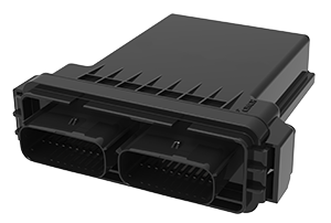
M130 CAN Gateway ECU
Capabilities
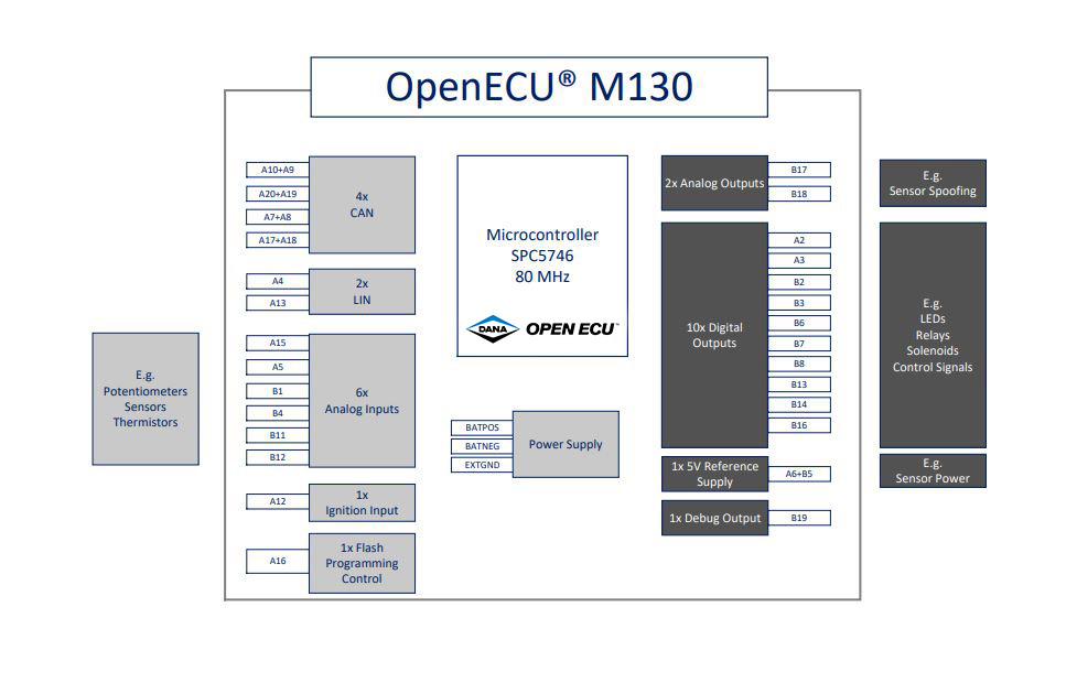
- Advanced 32-Bit NXP Microprocessor
- SPC5746B
- 80 MHz
- Up to 3MB code space
- Up to 256kB RAM space
- Up to 256kB Calibration space
- 4 high speed CAN 2.0B/ CAN-FD channels
- Wake on CAN (CANA)
- 2 LIN channels
- Ignition Input
- Total of 6 Analog/Digital inputs
- 2 RTD capable analog inputs
- Software configurable delayed power off
- 2 Analog voltage output channels
- 1 5V 200mA sensor power supply output
Some of the Possible Applications
- CAN Gateway Module
- CAN to LIN Gateway
- CAN I/O Expansion Box
- Smart Relay Driver
- Embedded System Control and Supervisor
- Alternative Fuel System Controller
Hardware Specifications1
| Communications | |
| CAN-FD | 4x |
| LIN (master)2 | 2x |
| Inputs | |
| Ignition | 1x |
| Analog | 6x |
| Outputs | |
| 500mA LSD | 6x |
| 2A LSD | 4x |
| 5V Sensor Power Supply | 1x |
| 0-5V Analog ±10mA | 2x |
| Electrical | |
| Output Protection | Short to Battery, Ground |
| Battery Input Protection | Overvoltage, Reverse Voltage |
| Operating Voltage | 8V to 32V |
| Survive Voltage | -28V to 36V |
| Other | |
| Program Status LED drive | 1x |
| Reprogramming Enable In | 1x @18V |
| Electromagnetic Compatibility (Targeted) | |
| Conducted Emissions | CISPR25 Class 2 |
| Radiated Emissions | CISPR25 Class 2 |
| Immunity | ISO 11452-4 |
| Conducted Transients | ISO 7637-2 |
| ESD | SAE J1113-13 |
| Physical | |
| Dimensions | 138 x 130 x 42 mm (L x W x H) |
| Material | PPA GF33 |
| Connectors | 2 x 20 pin (Molex MX150) |
| Vibration | ISO 16750-3 Test VII |
| Environmental Protection | IP67 – sealed |
| Operating Temp | -40°C to 85°C |
1For full details please refer to the full M130 Technical Specification
2LIN slave mode on 1 channel can be offered as a population change option
BLOCK DIAGRAM
DOWNLOADS
- M130 Flyer
- M130 Technical Specification
- M130 Customer Interface Drawing
- M130 Pinout
- M130 CAD Model
- M130 IO Schematics
Please contact OpenECU support at support@openecu.com to get the compatible platform installer.
To view the complete list of our product downloads, please click here.
MODULE COMPARISON
Compare ALL OpenECU Modules
| M110 | M130 | M6 Family | M670 | Actuation | M560 | M580 | NX3 | CCU | DLC-12 | ||||||||||||
| Microprocessor | |||||||||||||||||||||
| Primary Processor | SPC5534 | SPC5746B | MPC5534 | MPC5674F | MPC5746B | SPC5746 | SPC5746 | Infineon Aurix | Infineon Aurix TC387 | Infineon Aurix TC364 | |||||||||||
| Primary Clock Rate | 80MHz | 80MHz | 80MHz | 264MHz | 160MHz | 160MHz | 160MHz | 300MHz | 300MHz | ||||||||||||
| Primary Code Space | 512KB | 3MB | 512KB | 3MB | 2302KB | 3MB | 3MB | Up to 3MB | Up to 4MB | ||||||||||||
| Primary RAM Space | 64KB | 256kB | 64KB | 128kB | 384KB | 256KB | 256KB | Up to 672kB | Up to 672kB | ||||||||||||
| Primary Calibration Space | 256KB | 256kB | 256KB | 128kB | 128KB | 256KB | 256KB | Up to 512kB | Up to 128kB | ||||||||||||
| Secondary Processor | SPC560P34 | SPC560P34 | SPC560P34 | ||||||||||||||||||
| Secondary Clock Rate | 64MHz | 64MHz | 64MHz | ||||||||||||||||||
| Secondary Flash Space | 192KB | 192KB | 192KB | ||||||||||||||||||
| Secondary Calibration Space | 20KB | ||||||||||||||||||||
| Secondary RAM Space | 12KB | 12KB | |||||||||||||||||||
| M110 | M130 | M6 Family | M670 | Actuation | M560 | M580 | NX3 | CCU | DLC-12 | ||||||||||||
| Power | |||||||||||||||||||||
| Operating Voltage | 9V to 32V | 8V to 32V | 12V or 24V | 8V to 18V | 8V to 18V | 8V to 18V | 8V to 32V | 9V to 32V | 9V to 32V | ||||||||||||
| Sensor Supply | 1x 5V @250mA | 1x | 2x 5V@250mA | 4x 250mA @ 5V | none | 2x 5V @200mA | 2x 5V @200mA | 1x 5V @250mA | 4x 5V @150mA each; 3x 5V @50mA each | ||||||||||||
| Standby Current | |||||||||||||||||||||
| Actuator Supplies | 1x 20A | 2x 10A @ Vbatt | |||||||||||||||||||
| Output Protection | Short to Battery, Ground | ||||||||||||||||||||
| Battery Input Protection | Overvoltage, Reverse Voltage | ||||||||||||||||||||
| Survive Voltage | -28V to 36V | ||||||||||||||||||||
| M110 | M130 | M6 Family | M670 | Actuation | M560 | M580 | NX3 | CCU | DLC-12 | ||||||||||||
| Communication | |||||||||||||||||||||
| High Speed CAN 2.0 | 2x | 4x | 2x | 4x | 1x | 4x | 4x | Up to 6x CAN-FD | 2x CAN-FD | 3x CAN-FD | |||||||||||
| LIN (master)2 | 2x | Up to 2x LIN | |||||||||||||||||||
| M110 | M130 | M6 Family | M670 | Actuation | M560 | M580 | NX3 | CCU | DLC-12 | ||||||||||||
| Inputs | |||||||||||||||||||||
| Inputs (Analog or Digital) | 10x | 6x | 18x (Digital: 6x; Analog: 12x) | 40x (Digital: 5x switched, 3x Frequency, PWM; Analog: 32) | 4x | 40x (Digital: 9x switched, 3x PWM; Analog: 28) | 44x (Digital: 9x switched, 3x PWM; Analog: 32) | Up to 18x | 9x | 22x, up to 29 optional | |||||||||||
| Reprogramming Enable (FEPS) | 1x @ -18V | 1x @ -18V | 1x @ -18V | 4x | |||||||||||||||||
| Differential VRS | |||||||||||||||||||||
| Single Ended VRS | |||||||||||||||||||||
| Frequency | Up to 9x | ||||||||||||||||||||
| Cam Shaft | 4x Hall only | ||||||||||||||||||||
| Crank Shaft | 1x Hall (VR option) | ||||||||||||||||||||
| RTD Sensor | 7x | 4x | |||||||||||||||||||
| Knock Sensor | Knock Sensor | ||||||||||||||||||||
| Lamda Sensor (UEGO) | 2x | ||||||||||||||||||||
| Lamda Sensor (HEGO) | 4x (only 2x available when using 2x UEGO) | ||||||||||||||||||||
| Ignition Sense | 1x | 1x | 1x | Included | |||||||||||||||||
| M110 | M130 | M6 Family | M670 | Actuation | M560 | M580 | NX3 | CCU | DLC-12 | ||||||||||||
| Outputs | |||||||||||||||||||||
| Low Current Low Side Drives | Up to 1x 20mA & 2x 100mA & 6x 500mA | Up to 6x 500mA LSD | 12x 100mA, 3x 400mA, 14x 700mA, 2x 1A | 11x 100mA, 4x 400mA, 14x 700mA, 2x 1A | 2x 1A, 7x 2A PWM, 4x 4A PWM | 2x | |||||||||||||||
| Medium Current Low Side Drives | Up to 4x 2A | Up to 4x 2A LSD | |||||||||||||||||||
| High Current Low Side Drives | 4x 2.2A, 1x 3.2A | 4x 2.2A, 1x 3.2A | |||||||||||||||||||
| 0-5 V Analog Output | Up to 2x 10mA | Up to 2x 10mA | |||||||||||||||||||
| PWM Low Side | |||||||||||||||||||||
| H-Bridge | 2x 8A | 1x 5A full-bridge & 2x 10A full-bridge or 4x 10A half-bridge | 2x 50A peak or 10A | 1x 10A, 2x 5A, 1x 3.2A | 1x 10A, 2x 5A, 1x 3.2A | Up to 4x | 1x 5A PWM | 2x 3A; 2x 7A PWM | |||||||||||||
| High Side Switch | 1x Hall (VR option) | 4x 1A, 5x 4A PWM | |||||||||||||||||||
| Low Side Injector | 3x 5A peak/ 2A hold | 8x software-programmable waveform peak-and-hold: nominal 25A peak, 15A hold | |||||||||||||||||||
| Current Monitors | 2x | Supported | Supported | ||||||||||||||||||
| Voltage Monitors | 2x | ||||||||||||||||||||
| High Side Logic Outputs | 2x 1mA | 2x 1mA | |||||||||||||||||||
| High Side Outputs | 4x 700mA | 4x 700mA | 4x 1A, 5x 4A PWM | 5x 20mA | 2x 100mA | ||||||||||||||||
| Low Side General Purpose, PWM (SM, VM, CTM) | 1x 10A, 1x 2A, 1x 500mA | 9x 0.2/0.5A lamp & relay, with monitoring of state, voltage, and fault status | |||||||||||||||||||
| Low-side General Purpose, Spark (SM) | 1x 8A | 8x (Smart Coil only) with monitoring of state; on-off mode for non-spark uses | |||||||||||||||||||
| High-side Injector sources | 2x Injector High-Side outputs with programmable boost voltage phase, 25A peak | ||||||||||||||||||||
| Low side GP (General Purpose) (VM, CTM) | 1x 8A, 2x 6A peak / 4A hold, with voltage and current-tripped monitoring | ||||||||||||||||||||
| High-side GP (General Purpose) (CM) | 2x 8A up to 85°C, intended for source to low-side outputs, with current monitoring | ||||||||||||||||||||
| Constant-Current (with inductive actuator) | 8x 2A | ||||||||||||||||||||
| M110 | M130 | M6 Family | M670 | Actuation | M560 | M580 | NX3 | CCU | DLC-12 | ||||||||||||
| Compatibility | |||||||||||||||||||||
| Vibration | ISO 16750-3 | ISO 16750-3 | Ford IIIB - Severe | ISO 16750-3 | IEC 60068-2-64 | ISO 16750 chassis mount | ISO 16750 chassis mount | ISO 16750 chassis mount | ISO 16750 chassis mount | ||||||||||||
| Environmental Protection | IP67 - Sealed | IP67 – sealed | IP67 Sealed/Gore vent | IP69K | IP69K & IPx8 Sealed/Gore vent | IP69K Sealed/Gore Vent | IP69K Sealed/Gore Vent | IP69K Sealed / Gore vent | IP6K9K Rated | ||||||||||||
| ESD | ±8kV - SAE J1113-13 | SAE J1113-13 | |||||||||||||||||||
| Conducted and Radiated Emissions | CISPR25 Class 2 | CISPR25 Class 2 | |||||||||||||||||||
| Conducted Transients | ISO 7637-2 | ISO 7637-2 | |||||||||||||||||||
| Bulk Current Injection Immunity | ISO 11452-4 | ISO 11452-4 | |||||||||||||||||||
| M110 | M130 | M6 Family | M670 | Actuation | M560 | M580 | NX3 | CCU | DLC-12 | ||||||||||||
| Physical | |||||||||||||||||||||
| Material | Plastic (PPA GF33) | PPA GF33 | Aluminum | Aluminum | Aluminum | Aluminum | Aluminum | Aluminum | Aluminum | ||||||||||||
| Dimension in mm (W x H x D) | 138 x 130 x 42 | 138 x 130 x 42 mm (L x W x H) | 228 x 158 x 50 | 266 x 299 x 56.5 | 207 x 104 x 45 | 225 x 205 x 45 | 225 x 205 x 45 | 163 x 160 x 40 | 258 x 194 x 41 | ||||||||||||
| Weight | 1.02 kg | 2.5 kg | 540g | 1.1 kg | 1.1 kg | 570g | 1.3kg | ||||||||||||||
| Connectors | 2 x 20 pin (Molex MX-150) | 2 x 20 pin (Molex MX-150) | 46 pin | Molex CMC 154-pin, 3-pocket | 1x 23 TE (AMSEAL) | Molex 112pin (1x 48, 2x 32) | Molex 112pin (1x 48, 2x 32) | 80 pins | Molex 36-pin | Molex 84-pin (3x28) | |||||||||||
| Location | Chassis mount | Engine Compartment/ Chassis | Engine Compartment / Chassis | Passenger Compartment | Chassis/Passenger Compartment | Chassis/Passenger Compartment | Light, commercial, and off-highway vehicles | Chassis mount | Chassis / Passenger Compartment | ||||||||||||
| Operating Temperature | ISO 16750-4 (-40°C to 85°C) | -40°C to 85°C | -40°C to 85°C | -40°C to 85°C | -40°C to 85°C | -40°C to 85°C | -40°C to 85°C | -40°C to 80°C | -40°C to 125°C | ||||||||||||
| M110 | M130 | M6 Family | M670 | Actuation | M560 | M580 | NX3 | CCU | DLC-12 | ||||||||||||
| Other | |||||||||||||||||||||
| Program Status LED drive | 1x | ||||||||||||||||||||
| Reprogramming Enable In | 1x @18V | ||||||||||||||||||||
 Accessibility