
OVERVIEW
Introducing M560
The OpenECU™ M560 Electronic Control Unit is designed with functional safety process for Vehicle Control Unit (VCU) and Vehicle Charge Control Unit (VCCU) to support the most demanding Electric Vehicle (EV) / Hybrid Electric Vehicle (HEV) supervisory control applications. Since most supervisory controls demand the highest level of functional safety, the M560 was developed as a Safety Element out of Context (SEooC) following ISO 26262.
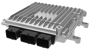
OpenECU M560
M560 ECU is supported by a high performance SPC5746 primary microprocessor and a powerful 32-bit SPC560P34 secondary microprocessor providing sophisticated, high-bandwidth rationality checking and system safety monitoring of full-authority vehicle control applications.
The M560 is designed to support EV / HEV supervisory control applications, the integrated charging circuitry eliminates the need for a separate charger interface module.
Due to its high quantity of customizable I/O, advanced microprocessor, safety-oriented architecture and user friendly OpenECU Simulink application interface, the M560 is a great rapid control prototyping platform for a broad range of applications. Dana also offers control algorithm for Electric Vehicle Model in MATLAB and Combined Charging System (CCS) suitable to support most EV / HEV / NEV architectures and following SAE J1772 and DIN 70121 standards. With the M560 or M580 Supervisory Control and Combined Charging System (CCS) control algorithms customers get an integrated module with Vehicle Control Unit (VCU) and Charge Management Unit (CMU) in one module i.e. two ECUs in a single controller.
Dana’s systems, controls and software engineers are available to support application implementations from prototype to production.
M560 is for 12v systems. Our M580 is specially tailored for 24v systems.
High Performance
- Powerful NXP SPC5746 microprocessor and 4x CAN 2.0 channels
- Multiple H-bridges, low side drives and high side outputs
- Comprehensive fault diagnosis supporting functional safety as well as OBD requirements
- High level diagnostics fault reporting resident in platform software
Versatile
- Designed to meet ISO26262 ASIL D functional safety requirements
- 112 pins of flexible I/O
- Integrated charging interface circuitry
- Truly open application independent Simulink® development environment
Capabilities
- Designed for complex hybrid and EV applications
- High-quality rugged hardware designed for Chassis or Passenger Compartment
- Supports common calibration tools such as ATI Vision and Vector CANape via CCP as well as Dana calibration tool OpenECU Calibrator
- Same proven hardware used for development can be used for volume production
- Supported platform software: OpenECU-FS
Hardware Specifications
| Microprocessor | |
| Primary Processor | SPC5746 |
| Clock Rate | 160MHz |
| Code Space | Up to 3MB |
| RAM Space | Up to 256kB |
| Calibration Space | Up to 256kB |
| Secondary Processor | SPC560P34 |
| Clock Rate | 64MHz |
| Total Flash Space | Up to 192kB |
| Total RAM Space | Up to 12kB |
| Inputs | |
| Digital Inputs | 9x switched, 3x PWM |
| Analog Inputs | 28 |
| Internal Features | |
| Partial Networking | Partial Networking |
| Wake on CAN (2 channels) | Wake on CAN (2 channels) |
| Wake on digital/PWM input | Wake on digital/PWM input |
| Pilot, Proximity and CC2 pins | Pilot, Proximity and CC2 pins |
| Application | |
| Location | Chassis/Passenger Compartment |
| Supply Voltage | 8 – 18V |
| I/O Summary | |
| Sensor Supplies | 2x 5V @200mA |
| Input Pins | 40 |
| Output Pins | 42 |
| Communication | 4x CAN 2.0 (primary processor), 1x CAN (secondary processor) |
| Outputs | |
| H-Bridges | 1x 10A, 2x 5A, 1x 3.2A |
| Low Current Low Side Drives | 12x 100mA, 3x 400mA, 14x 700mA, 2x 1A |
| High Current Low Side Drives | 4x 2.2A, 1x 3.2A |
| High Side Logic Outputs | 2x 1mA |
| High Side Outputs | 4x 700mA |
| Physical | |
| Dimensions | 225x205x45mm (WxDxH) |
| Material | Aluminum |
| Weight | 1.1kg |
| Connectors | Molex 112pin (1×48, 2×32) |
| Vibration | ISO 16750 chassis mount |
| Environmental Protection | IP69K Sealed/Gore Vent |
APPLICATIONS
M560 Applications Include:
VCU + VCCU (Integrated)The M560 provides capability for both VCU and VCCU application i.e. supervisory control and charge management in a single ECU.
| Application | Description |
| Vehicle Control Unit | Vehicle Control Unit (VCU) provides torque coordination, charge control, power management, thermal management, vehicle speed limiting and more for Electric Vehicle (EV) or Hybrid Electric Vehicle (HEV) architectures. |
| Vehicle Charge Control Unit | A Vehicle Charge Control Unit (VCCU) or Vehicle Communication and Charging Control (VCCC) is an ECU which manages the charging of Electric Vehicle or Hybrid Electric Vehicles. With Powerline Communication (PLC) the M560 provides charging circuitry for charging applications following SAE J1772, DIN 70121 standards. |
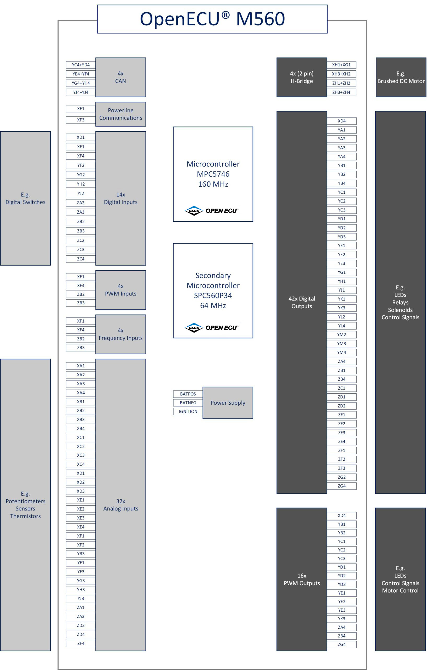
BLOCK DIAGRAM
CASE STUDIES
DOWNLOADS
- M560 Flyer
- M560 Technical specification
- M560 Packaging CAD Model
- M560 Customer Interface Drawing
- M560 Customer Pinout
OpenECU product downloads are available in our Download Library.
MODULE COMPARISON
Compare ALL OpenECU Modules
| M110 | M130 | M6 Family | M670 | Actuation | M560 | M580 | NX3 | CCU | DLC-12 | ||||||||||||
| Microprocessor | |||||||||||||||||||||
| Primary Processor | SPC5534 | SPC5746B | MPC5534 | MPC5674F | MPC5746B | SPC5746 | SPC5746 | Infineon Aurix | Infineon Aurix TC387 | Infineon Aurix TC364 | |||||||||||
| Primary Clock Rate | 80MHz | 80MHz | 80MHz | 264MHz | 160MHz | 160MHz | 160MHz | 300MHz | 300MHz | ||||||||||||
| Primary Code Space | 512KB | 3MB | 512KB | 3MB | 2302KB | 3MB | 3MB | Up to 3MB | Up to 4MB | ||||||||||||
| Primary RAM Space | 64KB | 256kB | 64KB | 128kB | 384KB | 256KB | 256KB | Up to 672kB | Up to 672kB | ||||||||||||
| Primary Calibration Space | 256KB | 256kB | 256KB | 128kB | 128KB | 256KB | 256KB | Up to 512kB | Up to 128kB | ||||||||||||
| Secondary Processor | SPC560P34 | SPC560P34 | SPC560P34 | ||||||||||||||||||
| Secondary Clock Rate | 64MHz | 64MHz | 64MHz | ||||||||||||||||||
| Secondary Flash Space | 192KB | 192KB | 192KB | ||||||||||||||||||
| Secondary Calibration Space | 20KB | ||||||||||||||||||||
| Secondary RAM Space | 12KB | 12KB | |||||||||||||||||||
| M110 | M130 | M6 Family | M670 | Actuation | M560 | M580 | NX3 | CCU | DLC-12 | ||||||||||||
| Power | |||||||||||||||||||||
| Operating Voltage | 9V to 32V | 8V to 32V | 12V or 24V | 8V to 18V | 8V to 18V | 8V to 18V | 8V to 32V | 9V to 32V | 9V to 32V | ||||||||||||
| Sensor Supply | 1x 5V @250mA | 1x | 2x 5V@250mA | 4x 250mA @ 5V | none | 2x 5V @200mA | 2x 5V @200mA | 1x 5V @250mA | 4x 5V @150mA each; 3x 5V @50mA each | ||||||||||||
| Standby Current | |||||||||||||||||||||
| Actuator Supplies | 1x 20A | 2x 10A @ Vbatt | |||||||||||||||||||
| Output Protection | Short to Battery, Ground | ||||||||||||||||||||
| Battery Input Protection | Overvoltage, Reverse Voltage | ||||||||||||||||||||
| Survive Voltage | -28V to 36V | ||||||||||||||||||||
| M110 | M130 | M6 Family | M670 | Actuation | M560 | M580 | NX3 | CCU | DLC-12 | ||||||||||||
| Communication | |||||||||||||||||||||
| High Speed CAN 2.0 | 2x | 4x | 2x | 4x | 1x | 4x | 4x | Up to 6x CAN-FD | 2x CAN-FD | 3x CAN-FD | |||||||||||
| LIN (master)2 | 2x | Up to 2x LIN | |||||||||||||||||||
| M110 | M130 | M6 Family | M670 | Actuation | M560 | M580 | NX3 | CCU | DLC-12 | ||||||||||||
| Inputs | |||||||||||||||||||||
| Inputs (Analog or Digital) | 10x | 6x | 18x (Digital: 6x; Analog: 12x) | 40x (Digital: 5x switched, 3x Frequency, PWM; Analog: 32) | 4x | 40x (Digital: 9x switched, 3x PWM; Analog: 28) | 44x (Digital: 9x switched, 3x PWM; Analog: 32) | Up to 18x | 9x | 22x, up to 29 optional | |||||||||||
| Reprogramming Enable (FEPS) | 1x @ -18V | 1x @ -18V | 1x @ -18V | 4x | |||||||||||||||||
| Differential VRS | |||||||||||||||||||||
| Single Ended VRS | |||||||||||||||||||||
| Frequency | Up to 9x | ||||||||||||||||||||
| Cam Shaft | 4x Hall only | ||||||||||||||||||||
| Crank Shaft | 1x Hall (VR option) | ||||||||||||||||||||
| RTD Sensor | 7x | 4x | |||||||||||||||||||
| Knock Sensor | Knock Sensor | ||||||||||||||||||||
| Lamda Sensor (UEGO) | 2x | ||||||||||||||||||||
| Lamda Sensor (HEGO) | 4x (only 2x available when using 2x UEGO) | ||||||||||||||||||||
| Ignition Sense | 1x | 1x | 1x | Included | |||||||||||||||||
| M110 | M130 | M6 Family | M670 | Actuation | M560 | M580 | NX3 | CCU | DLC-12 | ||||||||||||
| Outputs | |||||||||||||||||||||
| Low Current Low Side Drives | Up to 1x 20mA & 2x 100mA & 6x 500mA | Up to 6x 500mA LSD | 12x 100mA, 3x 400mA, 14x 700mA, 2x 1A | 11x 100mA, 4x 400mA, 14x 700mA, 2x 1A | 2x 1A, 7x 2A PWM, 4x 4A PWM | 2x | |||||||||||||||
| Medium Current Low Side Drives | Up to 4x 2A | Up to 4x 2A LSD | |||||||||||||||||||
| High Current Low Side Drives | 4x 2.2A, 1x 3.2A | 4x 2.2A, 1x 3.2A | |||||||||||||||||||
| 0-5 V Analog Output | Up to 2x 10mA | Up to 2x 10mA | |||||||||||||||||||
| PWM Low Side | |||||||||||||||||||||
| H-Bridge | 2x 8A | 1x 5A full-bridge & 2x 10A full-bridge or 4x 10A half-bridge | 2x 50A peak or 10A | 1x 10A, 2x 5A, 1x 3.2A | 1x 10A, 2x 5A, 1x 3.2A | Up to 4x | 1x 5A PWM | 2x 3A; 2x 7A PWM | |||||||||||||
| High Side Switch | 1x Hall (VR option) | 4x 1A, 5x 4A PWM | |||||||||||||||||||
| Low Side Injector | 3x 5A peak/ 2A hold | 8x software-programmable waveform peak-and-hold: nominal 25A peak, 15A hold | |||||||||||||||||||
| Current Monitors | 2x | Supported | Supported | ||||||||||||||||||
| Voltage Monitors | 2x | ||||||||||||||||||||
| High Side Logic Outputs | 2x 1mA | 2x 1mA | |||||||||||||||||||
| High Side Outputs | 4x 700mA | 4x 700mA | 4x 1A, 5x 4A PWM | 5x 20mA | 2x 100mA | ||||||||||||||||
| Low Side General Purpose, PWM (SM, VM, CTM) | 1x 10A, 1x 2A, 1x 500mA | 9x 0.2/0.5A lamp & relay, with monitoring of state, voltage, and fault status | |||||||||||||||||||
| Low-side General Purpose, Spark (SM) | 1x 8A | 8x (Smart Coil only) with monitoring of state; on-off mode for non-spark uses | |||||||||||||||||||
| High-side Injector sources | 2x Injector High-Side outputs with programmable boost voltage phase, 25A peak | ||||||||||||||||||||
| Low side GP (General Purpose) (VM, CTM) | 1x 8A, 2x 6A peak / 4A hold, with voltage and current-tripped monitoring | ||||||||||||||||||||
| High-side GP (General Purpose) (CM) | 2x 8A up to 85°C, intended for source to low-side outputs, with current monitoring | ||||||||||||||||||||
| Constant-Current (with inductive actuator) | 8x 2A | ||||||||||||||||||||
| M110 | M130 | M6 Family | M670 | Actuation | M560 | M580 | NX3 | CCU | DLC-12 | ||||||||||||
| Compatibility | |||||||||||||||||||||
| Vibration | ISO 16750-3 | ISO 16750-3 | Ford IIIB - Severe | ISO 16750-3 | IEC 60068-2-64 | ISO 16750 chassis mount | ISO 16750 chassis mount | ISO 16750 chassis mount | ISO 16750 chassis mount | ||||||||||||
| Environmental Protection | IP67 - Sealed | IP67 – sealed | IP67 Sealed/Gore vent | IP69K | IP69K & IPx8 Sealed/Gore vent | IP69K Sealed/Gore Vent | IP69K Sealed/Gore Vent | IP69K Sealed / Gore vent | IP6K9K Rated | ||||||||||||
| ESD | ±8kV - SAE J1113-13 | SAE J1113-13 | |||||||||||||||||||
| Conducted and Radiated Emissions | CISPR25 Class 2 | CISPR25 Class 2 | |||||||||||||||||||
| Conducted Transients | ISO 7637-2 | ISO 7637-2 | |||||||||||||||||||
| Bulk Current Injection Immunity | ISO 11452-4 | ISO 11452-4 | |||||||||||||||||||
| M110 | M130 | M6 Family | M670 | Actuation | M560 | M580 | NX3 | CCU | DLC-12 | ||||||||||||
| Physical | |||||||||||||||||||||
| Material | Plastic (PPA GF33) | PPA GF33 | Aluminum | Aluminum | Aluminum | Aluminum | Aluminum | Aluminum | Aluminum | ||||||||||||
| Dimension in mm (W x H x D) | 138 x 130 x 42 | 138 x 130 x 42 mm (L x W x H) | 228 x 158 x 50 | 266 x 299 x 56.5 | 207 x 104 x 45 | 225 x 205 x 45 | 225 x 205 x 45 | 163 x 160 x 40 | 258 x 194 x 41 | ||||||||||||
| Weight | 1.02 kg | 2.5 kg | 540g | 1.1 kg | 1.1 kg | 570g | 1.3kg | ||||||||||||||
| Connectors | 2 x 20 pin (Molex MX-150) | 2 x 20 pin (Molex MX-150) | 46 pin | Molex CMC 154-pin, 3-pocket | 1x 23 TE (AMSEAL) | Molex 112pin (1x 48, 2x 32) | Molex 112pin (1x 48, 2x 32) | 80 pins | Molex 36-pin | Molex 84-pin (3x28) | |||||||||||
| Location | Chassis mount | Engine Compartment/ Chassis | Engine Compartment / Chassis | Passenger Compartment | Chassis/Passenger Compartment | Chassis/Passenger Compartment | Light, commercial, and off-highway vehicles | Chassis mount | Chassis / Passenger Compartment | ||||||||||||
| Operating Temperature | ISO 16750-4 (-40°C to 85°C) | -40°C to 85°C | -40°C to 85°C | -40°C to 85°C | -40°C to 85°C | -40°C to 85°C | -40°C to 85°C | -40°C to 80°C | -40°C to 125°C | ||||||||||||
| M110 | M130 | M6 Family | M670 | Actuation | M560 | M580 | NX3 | CCU | DLC-12 | ||||||||||||
| Other | |||||||||||||||||||||
| Program Status LED drive | 1x | ||||||||||||||||||||
| Reprogramming Enable In | 1x @18V | ||||||||||||||||||||
 Accessibility