Overview
The OpenECU® Sim-API is a Simulink® blockset that allows users to rapidly develop Model-Based applications using hardware inputs/outputs and operating system targeting both rapid prototyping and production ECU applications. Sim-API is seamlessly integrated into MATLAB® to provide a complete toolchain from concept to software build. Sim-API has been used on hundreds of rapid prototyping projects and multiple series production applications over the last decade.
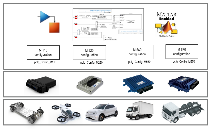
OpenECU and OpenECU-FS Developer API for Simulink® allows developers to develop Model Based Control Applications directly on production level target Electronic Control Units (ECUs).
OpenECU® and OpenECU-FS are suitable for electric vehicles, eVTOL, heavy duty or commercial vehicle applications.
Clean Simulink API for Model Based Development
OpenECU provides a complete software build environment. From within Simulink, press CTRL-B on the model and the rest of the build is fully automated. Code generation is handled by Mathworks Simulink Coder or Embedded Coder. When MathWorks has completed the code generation, OpenECU will compile the generated code and link it to the OpenECU operating system libraries. Additionally, OpenECU creates ASAP2 files to support common third-party calibration tools such as ETAS Inca, ATI Vision and Vector CANape. The build is completed with the creation of the ASAP2 and .s37 files ready to be flashed on the ECU.
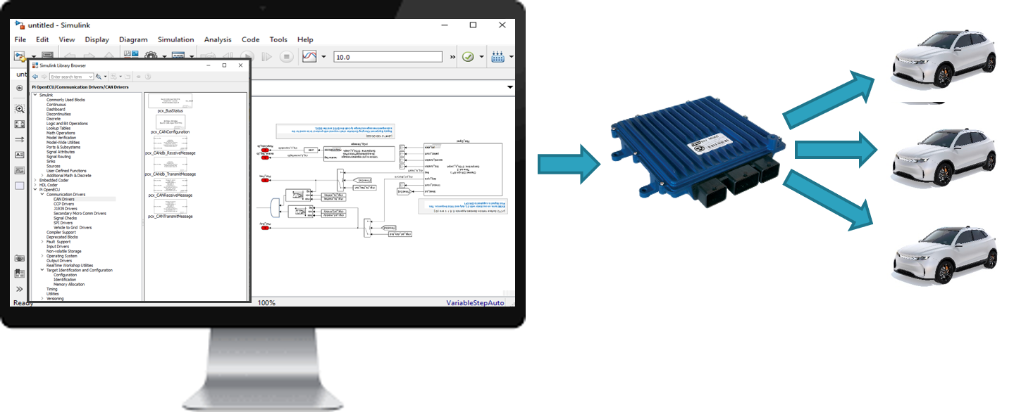
ECU Software Development with Rapid Control Prototyping on Production ECU Target
Simulink® Developer API: Sim-API
Sim-API contains more than 180 unique Simulink blocks designed to provide the ECU configuration, input handling, and output drivers for all the OpenECU hardware products.
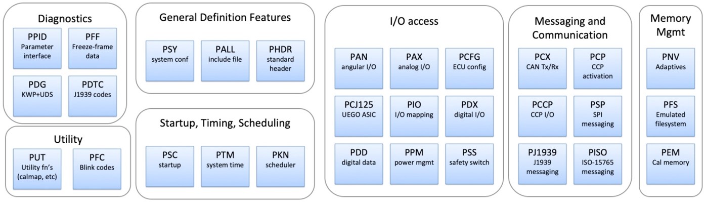
OpenECU Simulink Blocks Designed for OpenECU Hardware
OpenECU Messaging, Communication, & Diagnostics
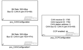
CAN and CCP Configuration Simulink Blocks
CAN Configuration blocks are used to specify the baud rate of a CAN bus in the application model.
CCP Configuration blocks specify the CAN Rx/Tx IDs for reprogramming, calibration and debugging the target controller
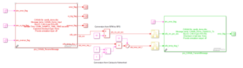
CAN DBC Receive and Transmit Message Blocks
The CAN db Receive Message blocks specify messages from a DBC file to read on the CAN bus. They can be configured to read specific signals in the message if not all are desired. The block is automatically updated to show only those output signals explicitly specified.
CAN db Transmit Message blocks similarly specify messages and signals to be transmitted on the CAN bus.
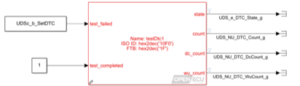
Diagnostics (J1939, UDS, DTCs, PIDs etc.) Simulink Blocks
OpenECU offers libraries for easy configuration of different CAN standards and protocols including:
- J1939
- ISO-15765
- Diagnostics (OBD, UDS, DTCs, PIDs etc.)
OpenECU Inputs
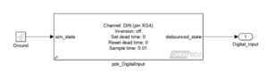
Digital Input Simulink Blocks
The Digital Input block reads an input channel and reports its digital state. Configuration for this block includes sample time, inversion, and debounce logic.
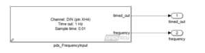
Frequency Input Simulink Blocks
The Frequency Input block reads an input channel to determine its frequency. Configuration for this block includes sample time and a timeout threshold.
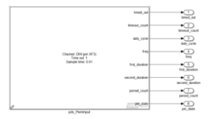
PWM Input Simulink Blocks
The PWM Input block reads an input channel and determines several characteristics including duty cycle, frequency, time out, etc.
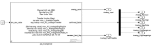
Analog Input Simulink Blocks
The Analog Input block reads an input channel and converts it to an engineering value after checking for faults configured in the block parameters.
OpenECU Outputs
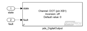
Digital Output Simulink Blocks
The Digital Output block reads receives a Boolean state and sets the output channel pin accordingly. A fault condition sets the pin state to the default value set in the mask.
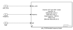
PWM Output Simulink Blocks
The PWM Output block receives a duty cycle and frequency command and pulses the output channel pin. The block parameters allow the user to set phase offset, inversion, duty cycle limits, and default values.
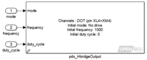
H-Bridge Output Simulink Blocks
The H-bridge Output block receives a duty cycle, frequency, and mode command and drives the channel pins accordingly. Four modes can be commanded:
- no drive (0 – all switches open),
- brake (1 – high-side switches closed),
- forward (2) or
- reverse (3 – one side is connected to high-side while the other is modulated to ground at a programmable frequency and duty-cycle).
Seamless OpenECU Simulink Integration
OpenECU® is compatible with all native Simulink® functions.
Stateflow
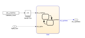
OpenECU with Stateflow
Stateflow provides a readable, graphical environment in Simulink for writing sequential logic or state machines. E.g.,
- Controller State: Off, Sleep, or On
- Gear Position: Park, Reverse, Neutral, or Drive.
- Ignition: On or Off
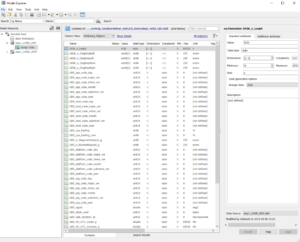
Simulink Data Dictionaries
Simulink Data Dictionaries
Simulink Data Dictionaries provide a searchable repository to define variables for a model. This is useful for defining enumeration and calibration values, data types, accuracy, and matrices.
S-functions
S-functions allow users to incorporate hand-written C, C++, or Fortran into their model. This can be used to create custom Simulink blocks.
Help Documentation
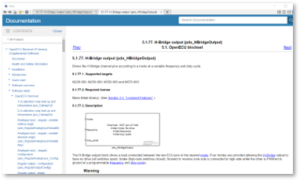
OpenECU Help Documentation
OpenECU blocks provide help documentation in the Simulink environment with the level of detail used to describe the native Simulink blocks. This helps users easily access information to incorporate OpenECU blocks into their Simulink models with efficiency.
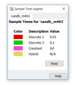
Sample Time Setting
Sample Time Settings
The sample times defined in the Simulink model defines the execution loop rate of the application on the ECU. Simulink’s color-coded signals make it easy to understand how the model is executed on target.
 Accessibility