
Introduction
Traditionally, replacing an OEM engine ECU or Engine Control Module (ECM) has almost always been out of the question. OEMs exercise proprietary rights to the hardware and software design used for engine control. This can often cause an undesirable delay, or even lead to a complete halt on advanced engine research programs or testing of new components on a base engine. Often, automotive organizations looking to modify ECU behavior face a big setback due to lack of access to engine controls.
Dana has developed a systematic approach to replace OEM ECUs (ECM) allowing full access to software and calibration, for prototypes, advanced technology development, demonstration fleets, or low to medium volume production programs. This is established with a combination of Dana’s engineering team expertise and the OpenECU family of rapid control prototyping ECUs and software suite. OpenECU is implemented to volume production standards and offers an accessible platform for custom configuration, adaptation, and further development. The goal is to provide a baseline engine control to customers to allow them to focus on what they do best.
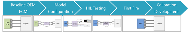 Figure 1: Dana’s approach for OEM ECU replacement
OEM ECU Replacement Process
1. Baseline the OEM ECU
The first step in this process is understanding the OEM ECU inputs and outputs, and mechanical configuration of the engine. Requirements capture related to characteristics of sensors and actuators is a critical step to confirm the compatibility of the engine system with the right OpenECU hardware. This is done using a customer questionnaire and preliminary review of available datasheets for different engine components. M670 is commonly used for engine control applications. M670 can also be customized to meet specific customer requirements.
In situations where data sheets for sensors are unavailable, and actuator characterization or trigger wheel patterns are not known, we use a bespoke break out box (BoB) and in-line connector setup allowing access to all the pins of the OEM ECU.
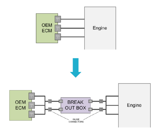 Figure 2: Setup for baselining the OEM ECU
This setup is then used to develop transfer functions for sensors, establish crank and cam patterns, and analyze output waveforms using dual instrumentation methods, oscilloscope measurements, etc. Important parameters are recorded to develop the baseline performance dataset. Some of the typical measurements made are:
- Injector timing and duration
- Number of injections
- Voltage and current recordings of actuators
- Fuel pressure for various speed and load conditions
A pin-out sheet to assign the available I/O to the relevant pins of the selected OpenECU module is drafted, which is the next step prior to model configuration and hardware-in-loop (HIL) testing.
2. Model configuration
Model-based control design (MBD) has gained significant momentum in the automotive industry to accelerate product development, while addressing the increased complexity of automotive systems, and reducing development time and costs. A rapid prototyping cycle is possible since MBD enables continuous simulation and verification of the control algorithm to allow early detection of errors, and the C-code is typically auto-generated which can then be deployed and tested on hardware.
At Dana, we have developed a model-based Generic Engine Control (GEC) strategy, which is accessible source code in the form of Simulink libraries (for both gasoline and diesel applications extendable to other fuel types such as LPG, CNG, etc.). These strategies are supported by documentation of the control architecture and software functional requirements for better understanding and knowledge transfer to the customer. The strategies can be used on OpenECU hardware to meet operating system needs. These strategies use floating point arithmetic and native Simulink blocks in the core of the application to allow for easier hardware target portability.
Within the model the crank, cam, and cylinder TDC configurations are appropriately set for the engine type. An application-defined sync logic based on crank and cam patterns is implemented to achieve engine sync. The OpenECU platform is designed in a way that allows software configurable waveforms for boosted/ non-boosted peak and hold injectors, saturating injectors and valves such as the fuel control valve, etc. that might require current controlled actuation.
The application is developed in a modular fashion and the required software modules can be integrated into the main model depending on the components involved in the application such as:
- Turbocharger
- Exhaust gas re-circulation (EGR)
- Variable valve timing (VVT)
The application incorporates a balance of first-principle physics-based modeling as well as 1D and 2D look-up maps, to characterize the underlying behaviors of different engine components. Commonly used functions are maintained in libraries and re-used to accelerate development and improve overall software quality. For production intent software, Dana focuses on the development of a modular architecture, which is essential since the software will go through inevitable expansion and refinement.
The model-based design approach lends itself to easy testing of the logic using simulation to prove the concept before integrating it with the main model. Further testing such as Model-in-Loop (MIL) and Software-in-Loop (SIL) testing can also be performed depending on the rigor required for the program.
The base calibration data available either from the customer or captured during the baselining process is integrated with the software before moving to the next step.
3. Hardware-in-Loop (HIL) testing
A one-click build system results in C-code generation: an S-record (s37) or Hex-record (hex) binary file along with an A2L file are generated. The A2L file contains all the information about measurement and calibration variables available in the control software and is typically utilized with industry standard calibration tools to communicate with the ECU via CCP.
The binary file is flashed on the OpenECU hardware, and HIL testing is performed with individual engine components to test basic functionality. This form of testing is made easier using calibratable overrides throughout the model. Crank and cam signals are setup using the HIL simulator, and the ability to achieve engine synchronization is verified first. OpenECU’s rapid control prototyping toolchain allows changes to be implemented and available on-target within a few minutes. This is of advantage for cases where there is interfacing with new components that might require quick software changes. After engine sync is achieved, injector firing and the waveform is verified along with actuation of other outputs such as spark, ETC, valves, etc.
This step also serves to identify any hardware changes that might be needed. Often a sensor might not function appropriately due to a different impedance than what is expected, and in cases like these OpenECU’s capability to be customized for specific system requirements becomes highly relevant. At Dana, this is referred to as an ECU ‘Option Control’. Some common changes in an option control are changing analog input pull resistance, changing low pass filter frequency of a digital input, changing pull-up source on analog and/or digital inputs, etc. Dana is also able to add completely new functionality to an existing OpenECU module depending on the specific needs of the customers such as 6-axis IMU addition to the OpenECU M670, piezoelectric pressure sensor addition to M670, etc.
After the option control exercise is completed and the available components are tested manually on the bench, the pin-out details are fixed, and the wire harness is developed by the customer.
4. First Fire
For this phase, a team from Dana typically arrives at a customer’s facility of choice. A dynamometer is used for the initial commissioning and calibration. The ECU is installed with the wire harness. One of the first steps is to perform signal and wiring checks for all sensors and actuators. If no issues are found, various key-on plausibility checks such as coolant temperature, battery voltage, etc. are performed. Crank and cam sync are established by motoring the engine without any combustion activity. This critical step ensures that engine sync is achievable which is necessary for enabling angular outputs/ actuators during normal operation.
At this point, the sensor transfer functions are also validated, and calibrated further as necessary. On the actuator side, angular outputs such as fuel control valve are verified against baseline data. Injector waveform and firing are confirmed by monitoring injector current and fuel rail pressure. If applicable, closed loop fuel rail pressure and cam phasing control are also tuned.
Once the operation of all the components is confirmed, the baseline calibration is verified. As a result, the engine is now able to operate with a new ECU.
5. Steady state calibration development
This step is intended for progress towards better engine operation with the new ECU. Traditional calibration refinement and verification activity in collaboration with the customer’s calibration engineers is performed. Steady state calibration is confirmed for various critical sections such as fueling, spark timing, target AFR, and cam phasing.
To further match OEM steady state performance, closed loop fueling, boost pressure control, and engine idling is tuned as well. Steady state operation across the engine’s nominal speed range is established.
A considerable amount of engine calibration is required to achieve the best performance from the engine control strategies, and once the initial steady state calibration is brought up to a pre-established customer expectation, a hand-off to the customer development team is performed. A training workshop is typically conducted at the end of the project to help the customer’s engineering team better understand the capabilities of OpenECU, along with new technology evaluations and understanding any future scope. Dana engineers train customer engineers while working alongside them to ensure the transfer of knowledge for full ownership.
CONCLUSION
OEM ECU replacement can be a tedious and complicated process. It can significantly affect advanced engine research programs, and customers looking to modify ECU behavior. With the OpenECU family of rapid control prototyping ECUs, and Dana’s expertise in system development and integration, you can accomplish ECU replacement seamlessly and in a short time frame.
Dana’s staged approach has been utilized in numerous engine programs. Dana can provide hands-on support with efforts ranging from commissioning and training on the OpenECU platform, through to providing full control software, hardware, and calibration, while being cost-effective and flexible.
To find out more about how Dana can help your organization replace an OEM ECU, develop a new prototype engine controller, or take your product from prototype to production, visit openecu.com or email info@openecu.com for more details.
 Accessibility