
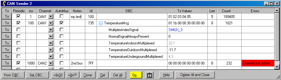
CAN Sender Window
Warning: sending CAN messages on a working system such as a vehicle may have unpredictable consequences. By using this program you accept all responsibility for such consequences, even if this program behaved incorrectly.
This window is created by doing Window… New CAN Sender (Ctrl-D).
It allows you to send arbitrary CAN packets either manually, or at regular time periods.
Use the ‘Notes’ column if you wish to remember the purpose of each message.
Note: see also the specialised ISO 15765-2 and J1939 windows if you wish to send messages encoded via those transport protocols, and also the CAN Monitor window for observing or logging CAN bus activity.
DBC File Use
The ‘DBC’ name is shown for any messages recognised from the loaded DBC files. See also DBC Setup help. You may expand such messages so that the numeric value for each signal can be accessed individually.
If a DBC file is loaded, you may type or paste the name of the message to set up a new row, as well as using the ‘From DBC…’ button. Multiplexed signals can be transmitted automatically; see AutoMux below.
You may drag and drop a message or individual signal to a Watch window for logging, viewing and graphing alongside internal ECU parameters.
One-off transmission

Clicking the Tx button for a message causes it to be sent once. If it is being sent periodically, the next message transmit time will be one period after this manual transmission.
Periodic transmission
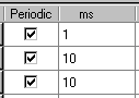
If the checkbox is ticked, this message will be sent automatically at the interval specified in milliseconds. The period for each message starts with its first transmission (or most recent manual transmission).
Note that the maximum bandwidth for CAN is about 4 messages per millisecond at 500 kbit/sec.
To transmit at fast rates (~1 ms) using a Kvaser interface, do Control Panel->Kvaser Hardware -> Global Settings -> CPU Load vs Response Time -> Settings and choose a more “Responsive” setting. Even then, bus saturation may not be possible.
Bus (channel)

You may select any of the CAN buses currently defined to transmit each message on (see Hardware window).
Message ID

The transmit ID is interpreted as hexadecimal. Any ID greater than 0x7FF is interpreted as an extended (29-bit) ID. To send an ID in the 11-bit range in extended format, suffix the ID with an “x”, e.g. 7FFx.
AutoMux
See DBC help to understand multiplexed signals and how they are defined. They allow multiple signals to be sent in the same “space” in a CAN message, on a cyclic basis.
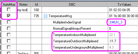
Messages containing multiplex signals can be cycled through the index (multiplexor) values automatically. If the AutoMux option is selected, the multiplexor value is moved to the next defined value after every transmit event (either manual or periodic). The CAN bytes are repackaged with the selected signal value(s) appropriate for the new multiplexor value.
The multiplexor signal is highlighted in blue. Currently selected signals are shown in black, and unselected signals in grey. If AutoMux is on and the message is being sent periodically, you will see the multiplexor value and signal colouring ripple through the different values.
The values for each signal are saved in the workspace. If the multiplexor is set to a new value which selects a signal you have never edited, it starts with a value of zero. You may edit grey (unselected) signals.
Note: the window is refreshed on a human timescale (e.g. every 200 ms). A message being sent much faster (e.g. 10 ms) will cycle through the multiplex values as expected, but the screen display may not show all the values due to aliasing between the transmission rate and screen display rate.
Bytes to transmit
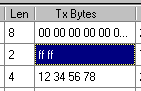
The transmit (tx) bytes are in hexadecimal. You can type in values by hand, or copy and paste from another program, or use the buttons at the bottom to set all 00 or FF (see below). The length in bytes is displayed. You may transmit between 0 and 8 bytes in each CAN frame.
When a DBC-defined message is expanded into its individual signals, you may then edit the value for each signal individually, in its “engineering units”. The new value will be automatically converted into the equivalent CAN byte values ready for transmission.
Status
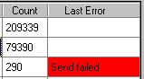
The number of messages queued for transmission so far is shown, and any errors reported. In this example, CAN2 is disconnected, so the transmit buffer of the CAN device became full.
Controls

The +8×00 and +8xFF buttons add a new message with 8 data bytes pre-filled to 0x00 or 0xFF respectively.
Use Clone to duplicate the current (last clicked-in) row to use as the basis for a new message.
The Del and Del All buttons remove messages from the list.
The coloured Go/Stop button allows you to turn CAN sending on or off for all messages at once.
The “text camera” button copies all data shown to the clipboard as text, so that it can be pasted into other programs.
If this window is closed, all of the settings and saved messages are lost. You can do this by clicking Delete All and Close. Otherwise, the current message set is saved as part of the workspace. To temporarily free up screen space without losing the settings for this window, minimise it.
The window can be scaled or maximised as required.
 Accessibility