
ECU Window
This window is created by doing File… New ECU (Ctrl-E).
ECU stands for Electronic Control Unit, i.e. the embedded system you wish to work with.
An ECU has one set of symbols (variable and function names and addresses) and one means of accessing its memory via a communications protocol.
If your system can be addressed as more than one logical node, even if it is one physical box, then define it as multiple ECUs in OpenECU Calibrator by using multiple ECU windows.
The ECU window must be present to work with your device, but can be minimised or reduced to a toolbar so that it does not use up screen space.
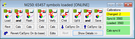
The title bar shows how many symbols have been loaded for this ECU. If none have been loaded, you will not be able to access variables by name, but other operations such as viewing memory or flash reprogramming will still work.
See also the OpenECU application note for worked examples.
File Operations
The most common operations each have a button at the top of the window. Clicking “Hide Details” reduces the ECU window to a toolbar showing only these buttons:
If a file operation is active, this is shown in colour. Here the buttons are also numbered for reference below:
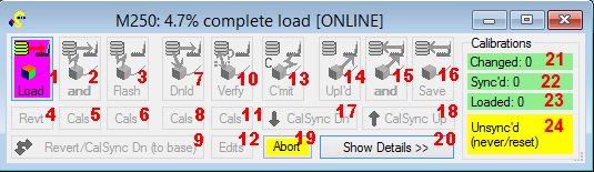
1. Load reads data from files and loads it into OpenECU Calibrator working memory on the PC. It does not download any data to your ECU. The type of data loaded depends on the file type and whether the Sym and Data checkboxes are ticked for each file:
- Symbols can be loaded from linker files (e.g. .ELF/.AFX/.OUT) or ASAP2 description files (e.g. .A2L). They are the list of variable and function names, types and addresses used by your program, used in Watch and Lookup windows. You may load symbols from more than one file, for example so that you can view variables for both a boot loader program and a main application program that are built separately and run in different areas of ECU memory. Similarly you can load both linker and ASAP2 symbols.
- Byte Data can be loaded from linker, parameter and hex/S-record (image) files. This data is shown instead of “live” data from the ECU if live data cannot be uploaded (e.g. if no ECU is connected). Data loaded from parameter (.c/.m) files is loaded to scratchpad memory and handled like edits. See memory help to understand colour coding and how base data is used in calibration. Image data is not contained in ASAP2 files.
2. Load and Flash performs both of these operations, and is typically used after you have created a new build of software. Use this to ensure that the symbols and data loaded to the PC are synchronised with the program and constant data in the ECU.
3. Flash transfers data from any file that has Flash ticked to ECU flash memory. This is typically used to load a new build of software or a saved set of constant calibration data for that build. Data from all selected files is loaded from disk first, and then the ECU is requested to erase all of the relevant areas of memory before each is programmed in turn. If symbols are loaded first, a C parameters file can be used to flash the ECU with specific data values at the correct addresses for the current build of software. Caution: programming constant image data from a previous build is likely to crash the ECU program as objects are likely to be located differently in a new build. Note also that this flashed file data, irrespective of values you have edited (see also Commit).
See also getting started: flash reprogramming.
4. Revert calibrations discards any changes you have made to values in the calibration area in PC scratchpad memory, going back to the default (base) values loaded from file. Use this button when the ECU is offline, because it does not attempt download to the ECU. If online, any live Watch, Lookup or Memory windows will quickly change the displayed scratchpad values back to the currrent ECU values. See also (9) below.
5. Load and Flash calibrations only does the same as Load and Flash, but while all data is loaded from disk, only the calibration area of ECU memory is reprogrammed. If you are sure the code area is unchanged, this is usually much faster than flashing the whole ECU.
6. Flash calibrations only similarly takes constant data from the selected files but reprograms only the calibration area of flash, without reloading symbols or file data to PC memory.
7. Download transfers data from any file that has Down ticked to the ECU RAM. The ECU is likely to reject the download if the area of memory does not exist, or is read-only. Caution: downloading new values to memory is likely to affect ECU program operation. In particular, image files that have been uploaded from a previous build should not be downloaded to a new build where variables and constants are likely to be located differently. However, C parameter files can be uploaded from one build and downloaded in another with compatible parameters, because the values are stored in an address-independent manner.
8. Download calibrations only is similar, but only locations in the calibration area of ECU memory are downloaded to. Other data from the selected file(s) is discarded.
9. Revert calibrations and download-synchronise replaces all values in PC memory with the original values loaded as file data, and downloads them to the ECU (reverts to base calibration). Use this when online to the ECU instead of (4) above.
10. Verify checks the ECU memory values against all the files selected for Data load. This can be used to check if an ECU already contains the code or data selected, e.g. for a particular software version. The symbol at which the first mismatch is found, if any, is reported.
11. Verify calibrations only is similar, but only checks values in the calibration area. Note that it checks against file data and not against scratchpad (edited) values in PC memory.
12. Verify calibrations including edits checks ECU memory values in the calibration area against current PC memory values, including any values you have edited. This operation is used automatically in some Resync options to determine if the ECU has “lost” values after a reset.
13. Commit calibrations uses the current data in PC scratchpad memory to reprogram the calibration area of the ECU flash only. Use this to immediately “fix” any calibrations you have modified so that they persist in the ECU when it is unpowered. Note parameters you have not been working with in PC memory will have their default values loaded from file unless you have uploaded them from the ECU, see (15) below.
14. Upload transfers data from the ECU memory (read-only or RAM) to PC scratchpad memory. The settings of each file (spanner/wrench button) dictate which areas of memory are uploaded.
15. Upload and Save performs both these operations in one step.
16. Save stores the current PC image of ECU memory to one or more PC disk files. Existing image files can be edited and resaved in OpenECU Calibrator when the ECU is offline, or new files created. The settings for each file (spanner/wrench button) affect what data is saved. See Understanding Memory for what data is saved.
17. Calibration synchronise-download sends the current PC memory values of all locations in the calibration area to the ECU memory, ensuring the PC and ECU have synchronised calibrations. This can be used when otherwise offline. This operation will only succeed if the ECU allows (RAM) download operations to the calibration area. If the ECU only has flash in the calibration area, use Commit (10) instead.
18. Calibration synchronise-upload is the reverse operation; this uploads all locations in the calibration area of the ECU to PC scratchpad memory, again ensuring the PC and ECU have synchronised calibrations. Again this operation can be used when otherwise offline, allowing subsequent editing of calibration values for an ECU that does not allow live edits to its calibration area.
19. Abort abandons the current operation in progress (there may be a delay of a few seconds).
20. Show/Hide Details expands the window to show the file list and other settings or shrinks it again to just the operation buttons.
21. Changed calibration bytes: the number of bytes in the calibration area in PC scratchpad memory which currently have different values to the original file-loaded (base) values.
22. Synchronised calibration bytes: the number of bytes in the calibration area in PC memory are known to have been synchronised with ECU memory via upload, download or flash operations.
23. Loaded calibration bytes: the number of bytes in the calibration area in PC memory which have had default (base) values loaded from file.
24. Calibration area status: indicates whether the entire calibration area is believed to be synchronised between PC memory and ECU memory. If the CCP protocol is in use, this detects ECU resets and shows synchronisation being lost if supported by the ECU.
File List
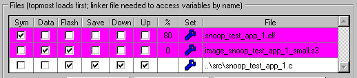
This list of files is used for all loading and data transfer operations. The top file is used first, so if two files contain overlapping data or duplicate symbols, the bottom file “wins”. Files can be re-ordered using the up/down arrow buttons or by dragging and dropping.
The meaning of the checkboxes by each file are highlighted in red above under File Operations.
During file operations, the file(s) in use are highlighted and the % column shows the approximate progress through the operation for that file. The latest file from disk is used in all operations, so it is not necessary to remove a file from the list and add it again if the file has changed (e.g. because of a new build).
Files are stored as both absolute locations and paths relative to where the workspace are stored. If the workspace and files it references are moved to a different directory, the relative paths are used if possible so that everything loads correctly from the new location. The relative paths are displayed, but hovering over a filename with the mouse shows the full absolute path.
Clicking the spanner (wrench) button opens a window to adjust the settings and properties for that file.
New files may be added by drag and drop onto OpenECU Calibrator or the ECU window specifically. Also, files may be dragged from the ECU window to your editor program for viewing.
Current file types supported
OpenECU Calibrator uses symbol information to display variables using their names, data types and sizes in Watch and Lookup windows.
OpenECU Calibrator uses constant data to display original values for parameters which can be viewed without an online ECU, and for flash reprogramming.
.ELF (DWARF symbols): the .elf file contains both binary data (program constant values and code) and symbols, the names, types and addresses of variables and functions. The extension .AFX is also used in the CodeWarrior environment. Read more on DWARF here.
Although the constant data in an .ELF file can be used for flash reprogramming, this will not work in build systems which modify that data (e.g. to add checksums) to produce a final binary image for download.
Different toolchains use certain ELF/DWARF features in different ways and not all tools have been tested with this program. Please try out the demo version with your toolchain and ask for support if you find your .ELF files are not processed correctly. In particular, it is essential to use a compiler or linker option to include DWARF debug data in the ELF file to access individual variables, which may need an additional compiler option like -g. Without the DWARF information, only basic section information will be present.
.OUT/.COF/.COFF (COFF2 with DWARF symbols): similar, as used by Texas Instruments targets. The symbols are taken from the DWARF debug information and not the COFF symbol table.
.A2L (ASAP2 symbols): the .a2l file contains a list of parameters (variables and constants) with their types and addresses, and metadata such as descriptions, units, and formatting requirements. Only symbols for the first ECU found in the .A2L file will be loaded.
.S /.S3 /.S37 / .S19 / .MOT (Motorola S-records): this is a human-readable text format containing hexadecimal raw data suitable for download. Typically an ECU build process results in such a hex file, which may contain additional or modified data compared to the .ELF file.
S-record files can be used to store small ranges of binary data from ECU memory, e.g. corresponding to calibration parameter values, as well as complete memory images for an ECU program.
The S-record format is described here.
.HEX (Intel HEX format): this is an alternative human-readable text format containing hexadecimal raw data suitable for download.
The HEX file format is described here.
.c (C-style parameters): if symbols are loaded from a linker file, then the values of parameters (constant or RAM variables) can be stored by name for upload, download and flash operations. This allows calibration values that have been adjusted in one software build to be stored, and later re-used with a new build of software in which those parameters have new addresses.
Options are provided to store data as C-style definitions (used to initialise constant data) or scalar assignments (executable at run-time). The statements are injected into C files between keywords so that you can udpate the source code used to build the software with uploaded values. For example:
/* SNOOP_CONST_PARAM_DEFINITIONS_BELOW */
		const volatile float stpm_lookup_2d_x[5] = {
		0, 500, 1000, 2000, 6000
	};
	const volatile float stpc_lookup_x = -2.718;
/* SNOOP_CONST_PARAM_DEFINITIONS_ABOVE */
.m (M-style parameters): these work similarly to C-style parameter files, but are saved in MATLAB M-file format.
.dcm (DCM parameters): these work similarly to C-style parameter files, but are saved in the portable DCM calibration format.
File Management

Add existing lets you browse for existing files to add to the list. You may add several files at once from the File Open window that opens. Adding a file to the list does not immediately open or download it in any way.
New image file lets you specify a new Intel HEX or Motorola S-record file in which data should be stored the next time an upload is performed.
New parameter file lets you specify a C file in which parameter values should be stored the next time an upload is performed. Those values can be subsequently reused with a different build of software to download or flash.
The arrow buttons let you shuffle the order of files. The order can be important as they are loaded in sequence, from top to bottom. If two files contain data covering the same area of ECU memory, the latter file “wins”. A C parameter file must be listed after the linker file which defines the symbols it uses.
The ‘cross’ button removes a file from the list. It does not actually delete the file on disk.
ECU Properties

You may change the ECU name here, but this is optional. The name cannot be blank, because it is used to identify the ECU in other operations.
Resync Options and Calibration Area define how adjustable parameters are handled in the ECU, and what should happen to them if the ECU goes through a reset or power cycle. See Calibration Help page.
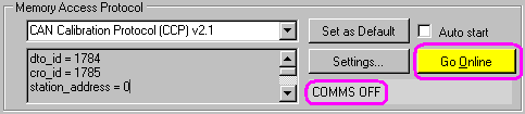
Memory Access Protocol
This section lets you set up the communication protocol that OpenECU Calibrator uses to communicate with your ECU and control whether the ECU is online.
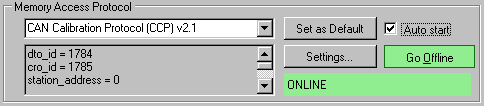
Online mode is selected by default. If the ECU is not currently responding, the status indicator (here “ONLINE”) turns red and explains the problem. Hover the mouse pointer over it to read the whole message.
If Auto start is checked, communication is always attempted with the ECU, but it may be turned off if required by clicking Go Offline. Whether new ECUs should have Auto Start selected can be set in File… Preferences.
Here offline mode has been entered by clicking Go Offline:
- In Online mode, live values from the ECU will be continually uploaded to Watch, Memory and Lookup windows, overwriting scratchpad memory values on the PC.
- In Online mode, any edits you make in Watch, Memory and Lookup windows will be immediately sent to the ECU as (RAM) download operations.
- In Offline mode, live values will not be uploaded automatically, but you may edit scratchpad values on the PC and manually upload, download or commit (flash reprogram) as described above. Use this to change flash parameters in ECUs that do not allow download to the flash area.
- In Offline mode, you do not need an ECU at all to work with parameter values loaded from files, and you may save new files with image or parameter data.
See also calibration help and memory help.
Currently the following memory access protocols are supported:
- CAN Calibration Protocol (CCP) v2.1; the default settings are thosed typically used with OpenECU’s OpenECU.
- Keyword Protocol 2000-3/ISO 14229-1 (UDS); you will probably need to adjust the default settings for your ECU. If your flash programming sequence is not satisfied by the program currently, please ask.
Communication Hardware Channel
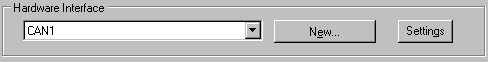
his section allows you to specify which hardware device and channel should be used for memory operations on this ECU. You may define a new hardware channel here if necessary.
Note that the hardware settings are not set here directly, because a single hardware interface may be used by different ECUs, and for diagnostic windows that are not “owned” by an ECU. Therefore a separate window for the relevant hardware channel is opened if you click “Settings” here.
See also Hardware Interface Window help.
ECU window controls

So long as the ECU window exists, this ECU can be used in other windows in OpenECU Calibrator such as Memory, Watch and Lookup windows.
Close everything for this ECU deletes all the ECU settings and closes this ECU window.
Minimise merely reduces the ECU window to a small bar which just shows the ECU name and number of symbols loaded.
Note that the ECU window size can be changed, which makes it easier to see a large list of files.
 Accessibility