

Problem Statement
An OEM developing Plug-in Hybrid Electric Vehicle (HEV) identified the need for a new Electric Park Brake (EPB) solution for its next generation of production vehicles. Dana was selected to deliver an EPB ECU solution leveraging OpenECU™ platform. Dana was responsible for ECU hardware development, design and integration of the application software using our rapid prototyping OpenECU software platform.
Dana was also responsible for executing production and functional verification and testing in accordance with ISO 26262. The highest safety goal for this Custom ECU project was rated to ASIL D as per the customer’s Hazard Analysis and Risk Assessment (HARA) and Functional Safety Concept (FSC). The VDA 305-100 standard for Recommendation for integration of Electric Parking Brakes control into ESC Control Units was referenced as a guiding document.
Electric Park Brake (EPB) architecture
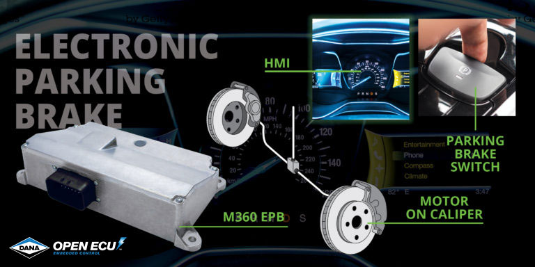
What is an EPB?
An Electric Park Brake (EPB) for automotive applications requires a park brake actuator to generate force on the brake disc to hold the vehicle in place, and an Electronic Control Unit (ECU) to provide power and control to the actuators. An EPB is typically used to replace the park-pawl functionality of an automatic transmission, and a mechanical handbrake’s emergency braking functionality.
Electric Park Brake (EPB) with M360
ISO 26262 Functional Safety
To develop this product in accordance with ISO 26262 for an ASIL D item. Dana follows the ISO 26262 V-model as shown. Dana was responsible for authoring the work products specified in ISO 26262 parts 4, 5, and 6.
- Part 4: Defines product development at the system level
- Part 5: For hardware level, and
- Part 6:For software level
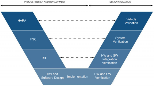
Functional Safety V-Model Process
Custom System Development
In accordance with ISO 26262 Part 4, system-level analysis was performed to ensure a safe system was designed. One purpose of the Part 4 work products is to identify all failure modes of the system and ensure a diagnostic or safety mechanism is in place for each failure mode. Functional safety process from Dana Custom ECU offering includes the following:
- Fault Tree Analysis (FTA) against the Technical Safety Requirements
- Dual Point Failure Analysis (DFP) and
- Design Failure Mode and Effect Analysis (DFMEA)
ISO 26262 (Functional Safety) Part 4
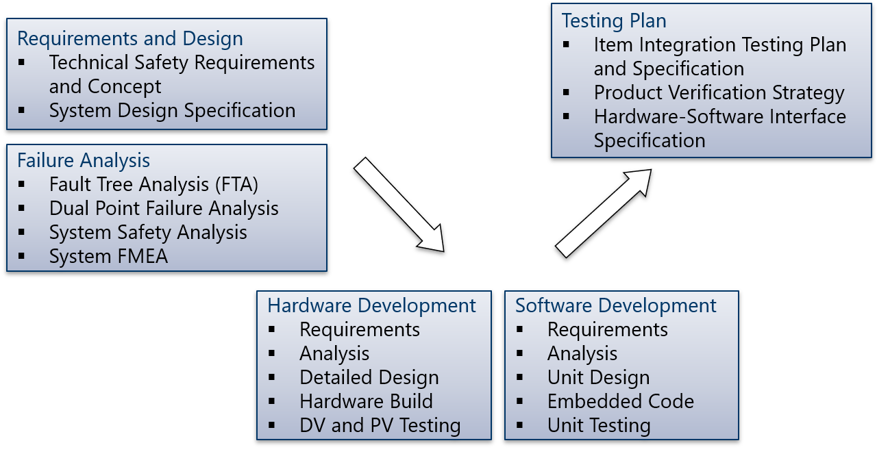
After the analyses were completed, an Item Integration Test Plan (IITP) was derived to define test objectives and methodology as it relates to testing the Hardware-Software Integration (HSI). Examples of ISO26262 Part 4 Work Products composed during this program include the following:
- Technical Safety Requirements and Concept
- System Design Specification
- Item Integration and Testing Plan, Specification, and Report
- Product Verification Strategy
- Fault Tree Analysis (FTA)
- Dual Point Failure Analysis
- System FMEA
- Hardware-Software Interface Specification
Custom Hardware Development
Hardware development for this program included creating a custom enclosure and Printed Circuit Board (PCB). Dana’s long standing history of development of Custom ECUs was heavily relied upon for developing a dual-micro-controller architecture to support high ASIL ECU as per the ISO 26262 process meeting the safety goals of the item.
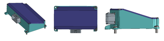
EPB hardware design
Additional features developed for this program include:
- High current H-bridge drivers
- Protection circuitry and
- EMC mitigation circuits.
Design and Verification Testing (DV Testing) and Production Validation Testing (PV) were performed to verify the hardware was developed to ASIL D.
Examples of ISO26262 Part 5 Work Products composed during this program include the following:
- Safety Plan
- Hardware Safety Requirements Specification and Verification Report
- Dependent Failure Analysis
- Hardware Safety Analysis and Report
- Hardware Design Specification and Verification
- FMEDA
Custom Software Development
To achieve ASIL D, a design choice was made to decompose the ASIL D software into two B(D) microprocessors: Primary and Secondary microcontrollers.
The Primary microcontroller software contains the park brake supplier’s application source code as well as Dana’s HOST application code, developed with the OpenECU platform.
In addition to park-pawl, park brake, and emergency braking functions, the application also uses the OpenECU diagnostics library to set and store trouble codes for UDS (Unified Diagnostic Service) diagnostic tools and send information to the vehicle HMI for driver notification.
The Secondary microcontroller acts as a safety barrier to the Primary micro by independently reading all the safety-critical signals of the system. It will prevent the HOST micro’s actuation commands if it independently detects an unsafe scenario.
The OpenECU platform and the application software for both microcontrollers were designed in accordance with ISO26262 Part 6.
Software features are developed in four steps:
- Software Architecture Design
- Low Level Requirements
- Code Implementation, and
- Software-in-the-Loop (SIL) testing.
Examples of ISO26262 Part 6 Work Products composed during this program include the following:
- Safety Plan
- Software Verification Plan, Specification, and Report
- Design and Coding Guidelines
- Tool Application Guidelines
- Software Safety Requirements Specification
- Safety Analysis Report
- Software Architecture Design Specification
- Dependent Failures Analysis Report
- Software Unit Implementation and Design Specification
- Embedded Software
Multiple-Supplier Collaboration
The VDA 305-100 Recommendation for integration of Electric Parking Brakes control into ESC Control Units provides guidelines for collaboration between multiple suppliers. The standard assumes that one supplier is responsible for the park brake assembly and its control algorithm while the other is responsible for the ECU and unit functionality software. It also differentiates the two parties as “PBC” (Park Brake Control) and “Host”. Dana served as the Host in this program and was responsible for allowing the PBC access to software and hardware components of the EPB ECU. The PBC was designed and developed by a third party partner.
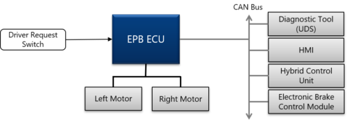
The Host software acts as a mediator between the PBC and the Hybrid Control Unit (HCU) and Electronic Brake Control Module (EBCM) and other components on the CAN bus. The Host is also responsible for driver alerts for fault conditions (over CAN) and setting diagnostic trouble codes. Other responsibilities of the Host include standstill manager, which is used to track the vehicle state (static or dynamic) and handle “apply” and “release” requests from the vehicle or driver.
Also, using the H-bridges to drive the park brake actuators as requested by the PBC and to provide voltage and current feedback are also responsibilities of the Host. Last, the Host is responsible for managing UDS requests, which includes relaying service routines to the PBC.
Hardware and Software Challenges
The two-microprocessor architecture of the EPB posed unique challenges in development. Software development was challenging because the microprocessors required freedom from interference from each other.
To accomplish this, the primary application software was developed using the OpenECU model-based suite while the secondary application was developed in hand-code C. Different compilers were used for both micros in order to ensure safety from common cause failures that may result from same tool-chains.
Results
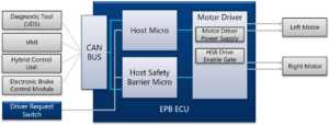
EPB Custom ECU block diagram
- Requirements Documentation
- Functional safety plan
- Software prototype delivered in 5 weeks
- Application Software included
- Delivery of hardware prototype in 4 months
- A-Sample
- Design Verification Plan (DVP&R)
- B-Sample Controllers
Dana produced a functioning hardware prototype of the ECU within four months of the project start date and a software prototype was available in five weeks. Allowing the brake actuator supplier to begin calibration early in the program. Dana has supported the customer on this program for over two years.
Tools Used
- MATLAB-Simulink
- OpenECU
- M360
- UDS
- OBD-II
- CodeWarrior IDE
- Wind River DIAB
- VectorCast
Keywords: EPB, Motor-on-Caliper, Functional Safety ECU, High Current ECU, M360
 Accessibility