
Formula SAE Team from the University of Michigan:
Michigan Electric Racing (MER) uses Dana’s M220 and M110 OpenECU controllers for Formula SAE Electric Vehicle.
About Formula SAE:
“SAE International’s Collegiate Design Series (CDS) competitions take students beyond textbook theory by enabling them to design, build, and test the performance of a real vehicle and then compete with other students from around the globe in exciting and intense competitions.”- SAE.
Michigan Electric Racing designs and builds an all-electric formula style race car every year. MER vehicles include many cutting-edge features:
- Independent, Dual Rear Wheel Drive
- Custom Battery Pack, designed from the cell up
- Custom Distributed Battery Management System
- Custom Motor Controllers
- Independent Torque Vectoring and Traction Control
- Live Data of three interoperable vehicle CAN Buses
- Full Aerodynamics Package, including front/rear wings, Undertrays, Diffuser, Side Wings, and Complete Body Work
- Rear Wheel Bump Steering
- Custom, In-House Manufactured Gearboxes, Spindles/Uprights, and other Suspension Components
- Advanced Driver Interface Controls and Feedback
Learn More about the team here
PLC Tuning
Power-Line Communication (PLC) is used during charging of electric vehicles around the world and is a must-have in today’s electric vehicle (EV) market. PLC allows the charging station (aka electric vehicle supply equipment or EVSE) and the EV to negotiate charging sessions, allowing various charging profiles and potentially to negotiate payment. Dana’s M560 and M580 modules have PLC capability built in.
Power-Line Communication (PLC) as depicted in ISO 15118-3 and DIN 70121 specifies power spectral density (PSD) limits of the HomePlug Green PHY PLC signal injection on the Control Pilot line for vehicle charging. HomePlug Green PHY is the standard for PLC signals used in vehicle charging called out in ISO 15118. Attenuation levels specified in the standards allow the differentiation between PLC signals on a connected charging station from crosstalk with a neighboring charging station. Higher than specified PSD on the PLC signal could cause disturbances in the Control Pilot detection, while having a signal too low could be interpreted as crosstalk or cause packet loss during the charging session. Having proper tuning provides the best environment for ensuring proper connection between a charging station and the electric vehicle.
Every vehicle model will have differences in mounting location and wiring harnesses for the charge controller module, which causes the attenuation on the Control Pilot line to vary. These differences may affect the entire spectrum of frequencies used for PLC, or only a subset. The default configuration of Dana’s modules will work in almost every situation, but with the different harness designs, there is the possibility of not meeting the DIN and ISO standards. Tuning, therefore, is essential for each vehicle model and Dana has the expertise on the tuning process of our M560 and M580 modules for use in our customer’s vehicle.
The maximum PSD of the PLC signal at the electric vehicle socket is -73dBm/Hz, with the target being -75dBm/Hz, as specified in ISO 15118-3. Dana can take measurements and, using some proprietary software, modify the PSD across the frequency spectrum to bring the entire PLC frequency band into compliance. Here is an example of a measurement taken on a pre-tuned and post-tuned module. Note that there are some frequencies with very low values, which are notched frequencies called out in the ISO and DIN standards. Additionally, note that the dBm value targeted is about -35dBm because with the resolution bandwidth used, the dBm/Hz ends up at the target of -75dBm/Hz.
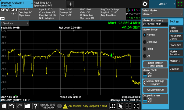
Figure 1 Module Before Tuning
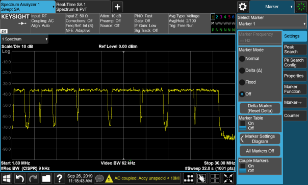
Figure 2 Module After Tuning
Once Dana creates an updated configuration for the customer’s vehicle, that configuration is used to program modules during production, eliminating the need for the customer to be concerned with having the correct configuration on the module. This configuration is not saved in the same memory as the application space, so the customer can continue to develop their vehicle application as usual.
Summary
- The OpenECU BMU is a rapid control prototyping embedded controller for Battery Management System (BMS).
- Provides control of the battery pack contactors and monitoring of the pack voltages and current
- Supports isoSPI cell monitoring unit (CMU) slaves selected by customer to provide a complete battery management solution
- Supports customers to develop BMS application using OpenECU Simulink or C API
- Hardware comprises of low voltage section and high voltage section.
Performance
- A dual microcontroller architecture providing redundancy with a main controller for control and secondary microcontroller for safety monitoring of the operations
- Designed to measure voltages in excess of 50V up to 1000V
- Includes the LTC2949 High Voltage Pack Monitor providing 8 channels capable of measuring 1000V
- Two current shunt inputs to calculate charge, energy and power flow into and out of the pack
Capable
- OpenECU, Dana’s base software (BSW) provides developers with Simulink® or C API for application development
- High-quality rugged hardware design for Battery Electric Vehicles and Hybrid Electric Vehicles
- Supports common calibration tools such as ATI Vision, ETAS INCA, and Vector CANape via CCP as well as Dana calibration tool OpenECU Calibrator
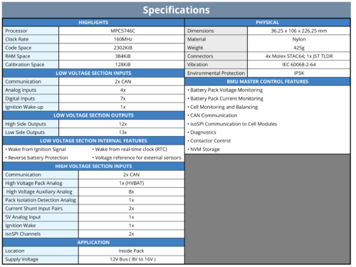
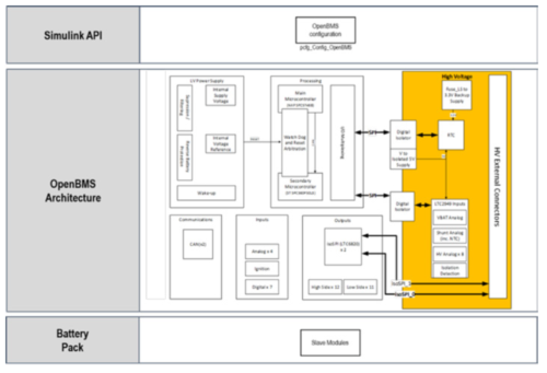
Dana’s BMU Master Controller is a rapid control prototyping embedded controller for Battery Management Systems. BMU Master Controller adopts isoSPI for communication with cell monitoring slaves. BMU Master Controller combines low voltage and high voltage in a single ECU providing cost optimized solution for our customers.

Dana has been a Kvaser Technical Associate (TA) and Qualified Sales Representative (QSR) for a number of years, and enjoys a good working relationship with this titan of the CAN (Controller Area Network) world! More than just using Kvaser CAN interface products as part of delivering embedded control solutions in development and in the production environment, we value Kvaser’s insights into the application of CAN in the transportation industries.

Being involved as part of the Kvaser TA network has been a valuable experience, bringing awareness of new developments in the CAN world, for example the introduction of CAN-FD, which offers the ability to access higher bandwidth and data rates. Another benefit that the relationship has afforded us is the opportunity to network with other TA organizations, with the chance to forge new business relationships, and to have some fun doing so as part or the regular TA meetings that the Kvaser team organizes.
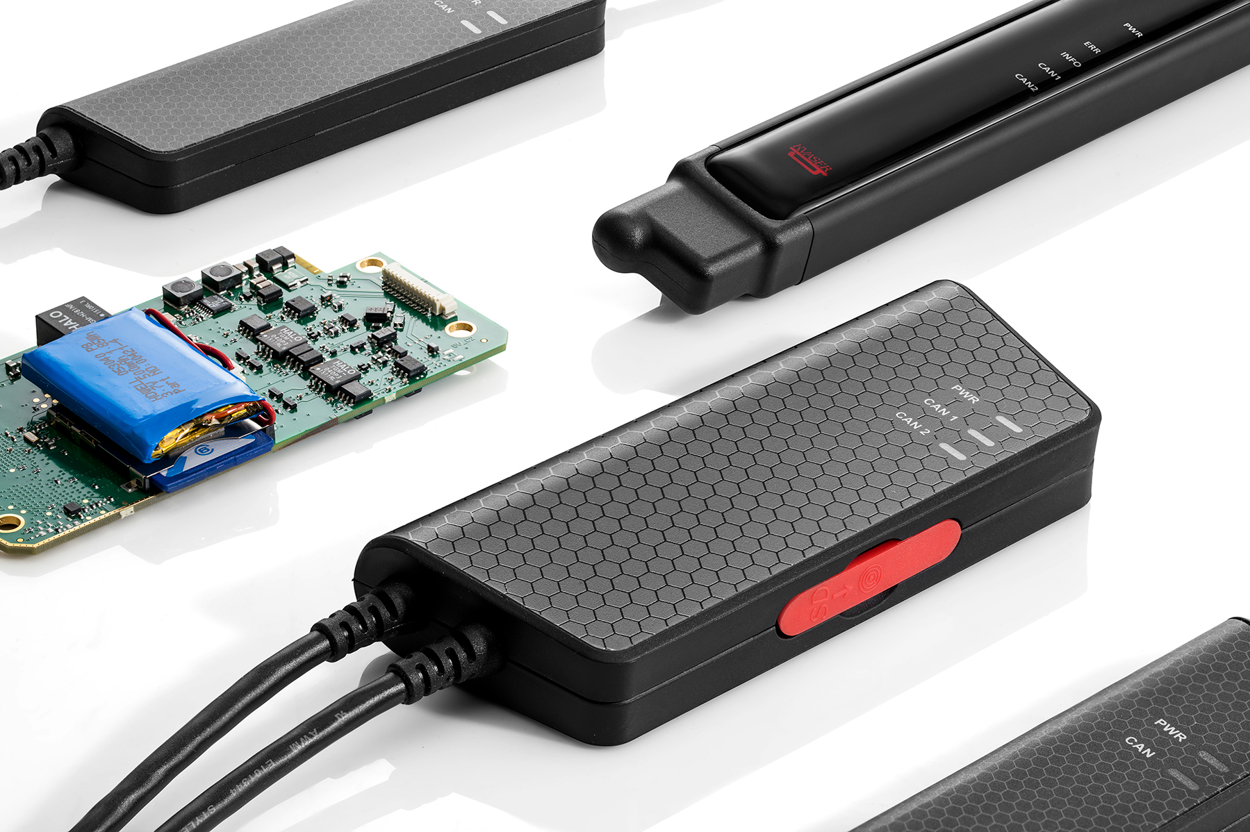
A good recent example of Dana’s collaboration with Kvaser was demonstrated during the EV Tech Expo in Novi, MI, where Kvaser’s Bryan Hennessy worked with Dana’s Amir Rezaei to showcase the capabilities of the OpenECU M560 controller running our CCS (Combined Charging System) base software and application strategies by simulating an EVSE (Electric Vehicle Supply Equipment) unit using Kvaser’s DIN rail product. More information about this effort was recently posted on the Kvaser website here: https://www.kvaser.com/simulating-an-electric-vehicle-charging-station-battery-show-demo-walkthrough/
DV BMU Emissions Test Issues
During development of our Battery Management Unit (BMU) we performed DV testing and found an issue in the radiated emissions test. Our schedule to meet the customers deadlines was tight so we did not perform pre-DV emissions scans which would have caught this failure earlier. We had to find a solution quickly to keep the BMU project on schedule so we needed to narrow down the root cause of the emissions failure, find a workable solution and test a prototype fix all within < two weeks? >.
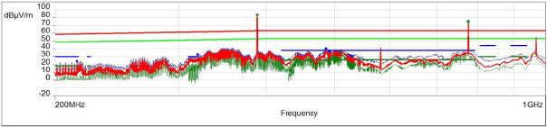
Figure 1 – BMU measured emissions (Peak, QP and Average) and corresponding limits
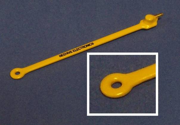 We quickly found the root cause of the emissions issue; using a near field magnetic field probe along with OpenECU’s spectrum analyzer our engineers found that the emitted noise was due to the SPI isolator integrated circuit (IC). That IC transfers the serial peripheral interface (SPI) signals and DC power from the 12V vehicle side of the BMU to the high voltage battery side for acquisition of the high voltage measurements such as the battery stack voltage. This device has internal transformers which transfer the power and signals across a 2500V isolation barrier. This requires high frequency switching to provide high efficiencies in the transformers. Switching noise internal to this part was being inserted into the high voltage side of our module and radiating out into the environment.
Dana engineers worked with the manufacturer of the isolator IC, Analog Devices Incorporated (ADI), to investigate the source of its noise. ADI engineers developed a reference design for this part that could pass automotive emissions tests but had found similar issues during their initial reference design work.
ADI engineers found that a capacitive current path was required to bypass the high frequency noise of the isolated DC/DC convertor back from the high voltage side of the board to the low voltage side. Also, filtering was required between the 5-volt isolated output of the device to the devices it powers on the high voltage side. ADI engineers recommended extending copper internal to the circuit board across the isolation barrier to provide an overlapping capacitive path. Our customer did not want to us to implement this approach because their research had indicated the possibility of breakdown of the isolation material in the printed circuit board over long-term use. Dana engineers modified a board to add high voltage rated capacitors across the isolation barrier along with filtering of the power output from the device.
Retesting the module for emissions indicated that these changes had reduced the noise below the acceptance levels of the test. Unfortunately, the re-test found that now the module was failing the test for susceptibility to the external noise. Dana engineers investigated this and realized that when the filtering to the power supply was added, the output impedance was increased to the point that the bypassing capacitance on the high voltage measurement parts was inadequate to overcome the injected noise a certain frequencies. Dana engineers calculated what capacitance was required, added the capacitors to the modified module and went back for another day of testing. This round the module passed the tests. A design with these modifications was ready for release with hours to spare before causing a schedule slip for the customer.
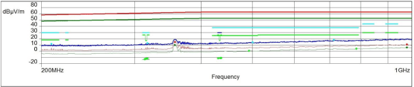
Dana recommends a project schedule includes a suite of pre-design verification tests which can be done at a reduced cost in time and money in development schedules. In this project these tests were not planned in order to meet an aggressive schedule and issues that the pre-DV testing would have found were not found until the DV testing. Fortunately, Dana engineers were able to find the source of the problem and a solution without causing a slip in the project schedule.
Summary
OpenECU®, Dana’s product line of off-the-shelf rapid control prototyping ECUs support integration with TargetLink. Users can import TargetLink subsystems into OpenECU Simulink models. Developers and test engineers can evaluate, and test algorithms developed with TargetLink on OpenECU hardware for fleet trials.
OpenECU Block
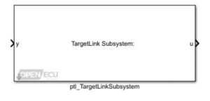 OpenECU integration has been simplified with the development of TargetLink Integration block available in OpenECU Developer Simulink-API.
The OpenECU TargetLink Subsystem block allows for easy import of production code from a subsystem developed in TargetLink.
The TargetLink model name, subsystem name, and input/output ports are specified in the block interface. One button causes the block to configure itself to have the specified interface. Another button launches the TargetLink code generator to generate production code for the TargetLink subsystem, imports the production code into the model at the block location, and imports the TargetLink data dictionary entries into the Simulink data dictionary.
Block Parameters
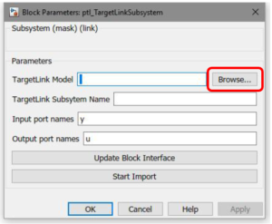 TargetLink Model
Press the “Browse…” button to browse for the model file. When the browse button is used, you will be prompted to select which subsystem from the TargetLink model file that you wish to import. All mask parameters will be automatically populated from the selected TargetLink subsystem.
TargetLink Subsystem Name
Enter the name of the TargetLink subsystem in the TargetLink model that you wish to import.
Input Port Names
Enter the names of the input ports for the block interface, separated by commas.
Output port names
The names of the output ports for the block interface, separated by commas.
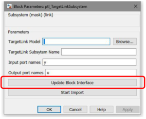
Update Block Interface
Clicking this button will update the interface of this block. Input ports will be created according to the “Input port names” parameter, and output ports will be created according to the “Output port names” parameter. Note that clicking this button will disconnect the block from the rest of the model as the block is re-drawn.
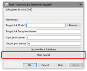
Start Import
Clicking this button will import TargetLink production code into the model at the current block location.
The TargetLink code generator is launched to produce production code from the TargetLink subsystem. All data entries in the TargetLink data dictionary associated with the selected TargetLink model will be imported into the Simulink data dictionary.
TargetLink Versions Supported
Currently, TargetLink version 4.4 (2018-B) has been tested and is supported. Newer TargetLink versions are expected to be compatible but have not been fully tested.
Refer to OpenECU Sim-API User Guide for more details or contact Dana at support@openecu.com or bd@OpenECU.com
Dana is proud to publish this whitepaper on Model-Based Design and OpenECU written by Arnav Gupta, System Engineer at Dana. Below is the summary of the whitepaper.
This whitepaper discusses the challenges faced by engineers while developing embedded control systems and focuses on software specific considerations within the model-based design (MBD) paradigm. It also sheds light on hardware considerations and highlights how an electronic control unit (ECU) development platform such as OpenECU®, can provide the complete solution for embedded controls development.
Today’s vehicles contain a complex technical infrastructure of various integrated systems. They have evolved from an aggregate of systems of mechanical components to systems with embedded electronic controls. Because of this evolution, embedded control systems are an integral part of vehicles today and even components such as traditional hand brakes are evolving into electronic parking brakes (EPB). While the traditional handbrake is simple and functional, an EPB enables additional functions such as automatic hill-hold and automatic brake-hold at stoplights. Additionally, it also frees up the space in the center console area contributing to interior aesthetics and enhances vehicle security, as the brakes can be locked when the vehicle is turned off and only unlocked with an authorized electronic key. With the traditional handbrake, information on failures is not available to the user, but electronic systems enable this – increasing both active and passive safety.
Download here for entire Dana Whitepaper
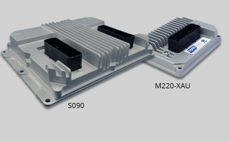
The M220-XAU is a unique variation of the M220 controller, specifically designed to be the master controller in applications using the S090 as a slave power driver box. This variation of the M220 provides inputs and outputs unique to motor control to seamlessly interact with the features of the S090 which include control of both a brushed and brushless DC motor.
The S090 is a versatile solenoid and motor drive slave power driver box optimized to support engineering development programs for the electrification of vehicular systems. It is designed for any system that uses PWM controlled actuators (valves, solenoids) and/or DC motors (brushed, brushless). It is an ideal solution for the most demanding actuators, capable of producing a total of 40A across its outputs.
- Designed to meet the needs of development engineers
- Die-cast aluminum sealed housing
- Proven sealed automotive connectors
- Robust electronics circuits suitable for an on-vehicle test environment
The combination of the M220-XAU with the S090 makes motor control simple by taking advantage of the M220’s existing VR sensor inputs and modified digital inputs, improved for high-frequency measurement. Software applications for using the M220-XAU as a master controller are streamlined with the availability of PWM outputs with synchronous sampling from the S090, providing feedback for measuring average motor line voltage, and decoders for measuring quadrature and 3-phase hall effect sensors.
Software Features include:
- Analog inputs synchronized to PWM Outputs Quadrature Decode Inputs (and Frequency Inputs)
- 3-phase Hall Decode Inputs
PWM outputs with synchronous analog inputs allow analog input signals (feedback from the S090’s motor drivers) to be read synchronously with the output waveform of the PWM control outputs of the M220. This analog input can be used for reading the average voltage for one of the 3-phase BLDC control lines.
The quadrature decode and frequency input provide a count of edges on the quadrature encoder since the last software iteration. This can be used to determine the encoder position or velocity.
This feature also provides the channel frequency for both the primary and secondary encoder sensors.
The hall decode input measurement decodes the signals from a 3-phase hall input, such as from a BLDC motor. This is compatible with 60° and 120° spacing configurations. This allows for accurate and consistent tracking of the motor angle in addition to speed, direction, and number of revolutions. This is often used to track the actuator position where the stop-to-stop motion requires several rotations of the motor.
Use Case
A Dana customer used the S090 for a high torque BLDC application for cold engine testing. The BLDC outputs of the S090 were used to drive an electric cam phaser. The master controller reads the speed of the internal combustion engine and subsequently commands the S090 to set the BLDC motor to the desired cam phaser position.
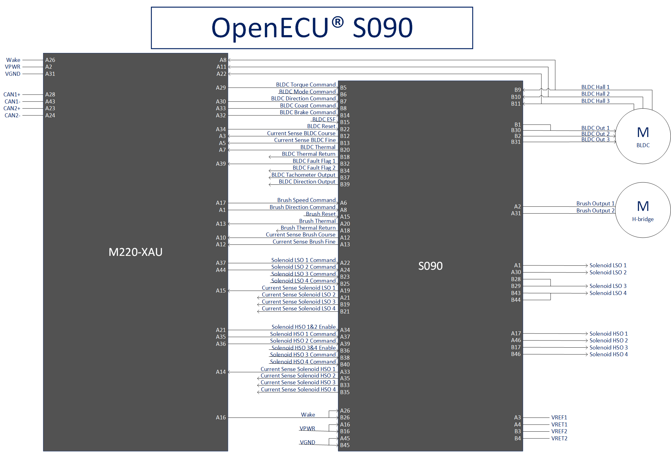
Proposed Pinout
The schematic below shows an example pinout of the M220-XAU paired with the S090.
Overview
Hexagon Studio was founded in 2005 with a vision to provide design and engineering services implementing turnkey solutions primarily in the automotive sector. The Hexagon Studio facility has been registered as an “R&D Center” by Ministry of Industry and Technology (Turkey) since 2011. A primary focus is electric vehicle integration and control software applications.
Dana’s OpenECU platform has been used in a range of EV/HEV projects and is currently in use by Hexagon Studio in several capacities. Erinc Topdemir – Technical Lead Engineer, R&D Center, Hexagon Studio shared reasons why they like using OpenECU:
- Fast Development – the same OpenECU module that is used for development can be put into volume production.
- No NRE (Non-Recurring Engineering) investment required to get proven cost-effective ISO 26262 ASIL D level production-quality VCUs (Vehicle Control Units).
- OpenECU is easy to use and has a proven software tool chain with a truly open Simulink® application-independent model-based development environment.
- Intellectual Property (IP) Ownership – by using OpenECU, Hexagon Studio has full control over all application IP developed and can make updates as required.
- Customization – Dana can customize the OpenECU hardware to provide the exact Inputs and Outputs (I/O) Hexagon needs to meet the application requirements.
- Engineering Support – Dana provides very responsive engineering support.
Vehicle Projects using OpenECU
Hexagon Studio’s Product Development System was used as a basis for systems engineering and requirement management in the following projects:
Wheelchair accessible taxi
The M250 OpenECU was used in a plug-in-hybrid taxi vehicle project as a vehicle controller. Dana supplied an EV & HEV control strategy including sample application and a generic requirement list for this program. By leveraging the Dana vehicle control strategies, Hexagon Studio was able to quickly develop a prototype vehicle. Torque, energy and thermal management strategies were added to provide control for features such as charging, discharging and regenerative braking.
EV Low-floor minibus
Hexagon Studio has used both the M670 OpenECU, and the M560 OpenECU for a low-floor minibus. The minibus is used as a public transport vehicle with an integrated wheelchair ramp for both the North American and the European markets. With the know-how and experience gained from previous projects, Hexagon Studio developed their own control algorithms based on customer requirements. The range extender control algorithm was developed to meet emissions requirements and has separate charge/range sustaining modes. The project evolved into a full EV by request of the customer in later stages.
Plug-in Hybrid Electric Vehicle (PHEV) Work Truck
The M670 OpenECU was used as the vehicle controller for the PHEV work truck. The PHEV with a 2-cylinder range extender was specifically designed to meet stringent work truck requirements to serve as a last mile package delivery vehicle for the North American market. This vehicle has both 2WD and 4WD options, and two body lengths. Hexagon Studio delivered multiple prototypes to the customer for durability testing and real-life delivery operations. This program also evolved into a pure EV and is now being prepared for production launch.
EV Three-wheeler cargo and passenger vehicle
The M110 OpenECU is used for the three-wheeler vehicle controller design. The 48V design includes special component selection and control. This vehicle is targeting last mile urban delivery applications where zero emissions and quiet operating performance are needed. Hexagon Studio leveraged EV control strategies developed on other programs to implement an optimized subset of strategies appropriate for this 3-wheel application.
35-foot EV Bus
M580 OpenECU is used in this full EV bus development. This project is based on a 650V architecture to enable the usage of readily available HV (High Voltage) components. Dana OpenECU modules are used for both VCU (Vehicle Control Unit) and as a gateway unit for combining components and supervising their controllers.
For all these projects, Hexagon Studio was responsible for implementing algorithms for vehicle traction, thermal management, charging control, energy management and component controls including traction inverters, DC/DC converters, and HV batteries. Electric vehicle Control Strategies were developed in Matlab/Simulink and validated with PIL (Processor-in-the-Loop) and HIL (Hardware-in-the-Loop) tests before starting the final validation on the prototype vehicles.
Some special features were designed and implemented for differing customer expectations and vehicle usage scenarios. The following solutions are offered depending on the customer’s requirements.
Solution
All of the Dana modules mentioned above have been used in testing vehicle control applications with a HIL device. Hexagon Studio is also capable of designing and incorporating into the HIL any kind of vehicle dynamic and all the main vehicle components. Performance and energy management calculations, functional tests, reliability checks and even design validation and durability tests are done with the help of these configurations. HIL testing at Hexagon Studios can use any of the Dana products covering all application types, vehicle types, and component functions.
Regardless of the hardware and project, fault diagnostics are also developed with OpenECU libraries. UDS, ISO-TP and ISO diagnostic algorithms are developed and integrated into the main control algorithm.
 Accessibility